
Anti-fouling apparatus and method

a technology of anti-fouling and anti-corrosion, which is applied in the direction of laboratory glassware, carpet cleaners, vehicle cleaning, etc., can solve the problems of increasing the demands on the user's time and money, affecting the accuracy of the measurement, and affecting the quality of the cleaning. , to achieve the effect of reducing the growth of biological foulants

Inactive Publication Date: 2008-03-11
MEASUREMENT SPEC
View PDF9 Cites 32 Cited by
  • Summary
  • Abstract
  • Description
  • Claims
  • Application Information

AI Technical Summary

Benefits of technology

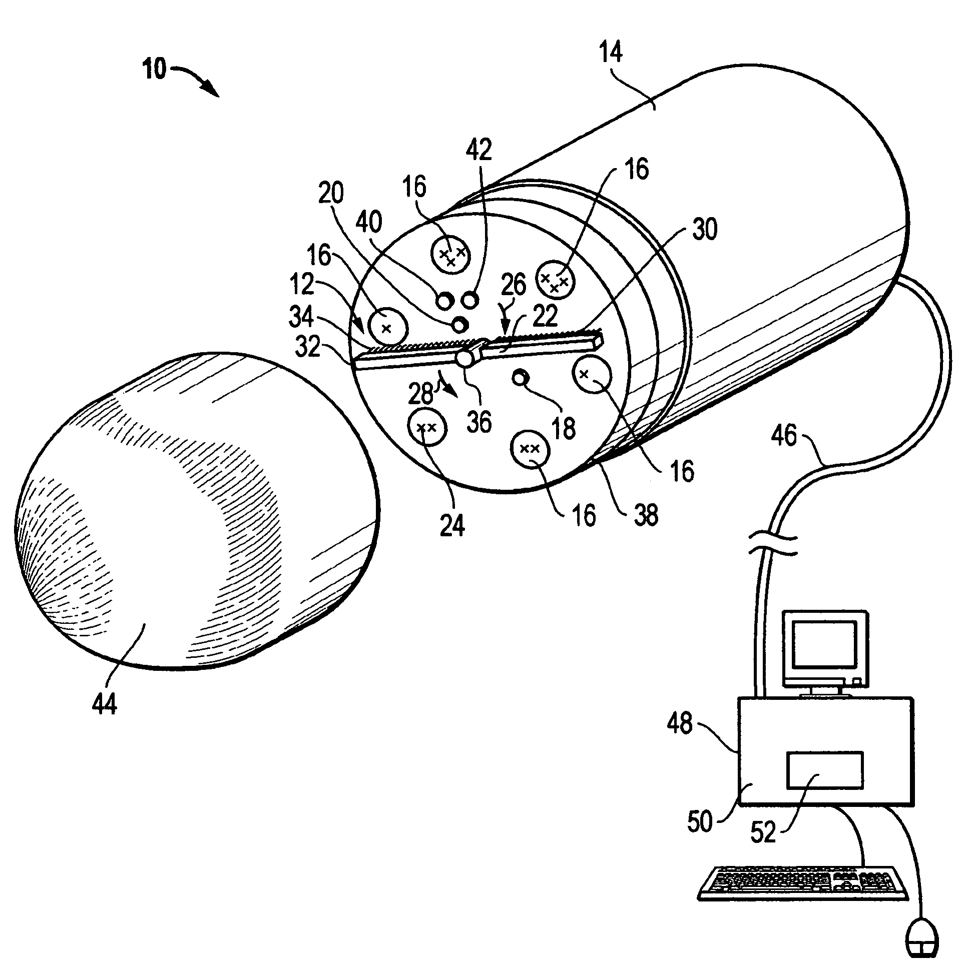
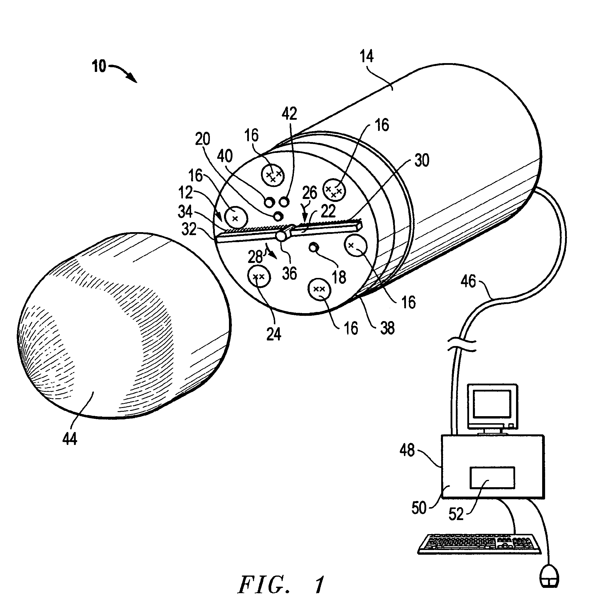
[0008]The anti-fouling apparatus and method of the present invention includes, according to one embodiment, a configurable cleaner connected to an object for physically removing foulants on the object. An ultraviolet (UV) light is connected to the object for reducing the growth of biological foulants on the object. The camera is connected to the object or sensors for observing the presence of foulants on the object and a configurable cleaner removes foulants from the UV light and the camera as well as from the object and / or sensors.

Problems solved by technology

A difficulty arises whenever instruments are utilized to measure anything.
Needless to say, despite the fact that this is very often if not always true, in most circumstances that degree of precision is not warranted and any errors due to the act of measuring itself are well within acceptable limits for error.
Instruments which cease to function accurately within accepted limits after only short periods of use increase demands on the user's resources of time and money.
Often, such sensors are continuously and progressively degraded by the fluids within which they are immersed (perhaps by the very analytes for which the sensors are designed) such that the instruments cease to accurately measure that which they are calibrated to do.
This is called “sensor drift” and might be caused by the nature of the sensor, its maintenance condition or by sensor fouling.
Sensor drift is a debilitating and expensive problem affecting sensors and sensor drift caused by fouling is of particular concern.
Fouling occurs when materials in the water(foulants) attach themselves to, and / or grow upon, a sensor to such an extent that the accuracy of the measurement deteriorates.
Such fouling can render the sensor inoperable, or even worse, allow subtle errors to contaminate a data set and cause erroneous data analysis.
Critical data is lost, and sensor operation and maintenance costs must increase to prevent additional data loss.
Often, however, the water to be analyzed contains biological and mechanical, living and inert, contaminants that can accumulate and / or grow on the surface of the sensors, causing the sensors' calibrations to drift, and possibly rendering the data useless or subtly misleading.
When multiprobes are deployed in waters containing foulants, the sensors will eventually become contaminated / fouled.
When sensors are deployed without protection against fouling they can only be deployed in fouling conditions for short periods.
Problematically, these prior art mechanical devices are difficult to apply to multiple sensors of different sizes and shapes, raise the price and complexity of individual sensors, complicate calibration, maintenance, repair, and operation even in non-fouling situations, and often suffer from high power consumption and poor control.
For example only, prior art devices utilizing biocidal coatings are incapable of preventing foreign materials from accumulating in the vicinity of the sensor or doing anything about an inert film, such as oil, that prevents accurate operation of the sensor just as much as any living material.
A similar problem exists with conventional optical sensors in that they can become contaminated by materials in the fluid, such as a algae in biologically active waters or sediment in industrial process waters.
This problem is complicated by the fact that the optical sensor may be only slightly altered and cause the operator to accept errant or misleading data or draw erroneous conclusions.

Method used


Image

  • Anti-fouling apparatus and method
  • Anti-fouling apparatus and method
  • Anti-fouling apparatus and method

Examples


Embodiment Construction

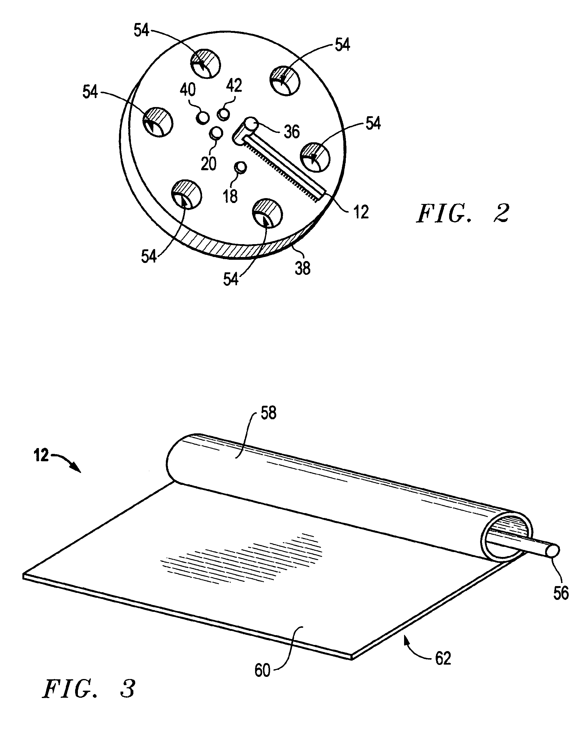
[0015]An embodiment of the present invention is illustrated by way of example in FIGS. 1-3. With specific reference to FIG. 1, anti-fouling apparatus 10, according to one embodiment of the present invention, includes a configurable cleaner 12 attached to an object 14. For the purposes of example only, and not by way of limitation, object 14 is represented as a multiprobe sensor device. As illustrated, object 14 includes many sensors 16. Sensors 16, as that term is used herein, an includes sensors for measuring temperature, dissolved oxygen, pH, gas constituencies, conductivity, turbidity, flow, color, biological activity, specific ionic activity, pressure, and oxidation-reduction potential, for example only. Any sensors 16 now known or hereafter developed are accommodated by the current invention. A UV light 18 and a camera 20 are connected to object 14. According to this aspect of the invention, configurable cleaner 12 is conformed to remove foulants from sensors 16, UV light 18, a...


PUM


Abstract

An anti-fouling apparatus and method includes a configurable cleaner connected to an object for physically removing foulants on the object. A UV light device is connected to the object for preventing the growth of foulants on the object and a camera is connected to the object for observing the presence of foulants on the object. The configurable cleaner removes foulants from the object as well as the UV light and the camera.

Description

FIELD OF THE INVENTION[0001]This invention relates to an anti-fouling apparatus and method. In particular, this invention relates to an anti-fouling apparatus and method for removing foulants from an object and for preventing the growth and / or accumulation of foulants on an object.BACKGROUND OF THE INVENTION[0002]A difficulty arises whenever instruments are utilized to measure anything. It has been said that no perfect measurement may ever be made for the reason that the very act of measuring the thing changes it. Needless to say, despite the fact that this is very often if not always true, in most circumstances that degree of precision is not warranted and any errors due to the act of measuring itself are well within acceptable limits for error. On the other hand, it is necessary for instruments to remain functioning at the highest possible levels for as long as possible for obvious reasons. Instruments which cease to function accurately within accepted limits after only short peri...

Claims


Application Information

Patent Timeline
Patent Type & Authority Patents(United States)
IPC IPC(8): B01L3/00B08B17/02
CPCB08B17/06B01L9/52B01L13/02
Inventor GARNER, STUART
Owner MEASUREMENT SPEC
Learn More