Air bearing and motor cooling

a technology of air bearings and motors, which is applied in the direction of positive displacement liquid engines, liquid fuel engines, piston pumps, etc., can solve the problems of reducing increasing the load on the thrust bearing used, and affecting the efficiency of the component providing the pressurized air, so as to improve the cooling flow path

Active Publication Date: 2008-03-11
HAMILTON SUNDSTRAND CORP
View PDF8 Cites 76 Cited by
  • Summary
  • Abstract
  • Description
  • Claims
  • Application Information

AI Technical Summary

Benefits of technology

[0009]Accordingly, the present invention provides improved cooling flow paths and a more efficient manner in which to provide the electric motor with cooling air.

Problems solved by technology

The imbalance of load on the bearings increases the load on a thrust bearing used to support the rotor assembly, which is undesirable.
Cooling the air is typically provided from a pressurized air source, which reduces the efficiency of the component providing the pressurized air.
Further, in the event of a failure of that component, flow of cooling air to the electric motor will cease possibly resulting in a failure of the electric motor.

Method used


Image

  • Air bearing and motor cooling
  • Air bearing and motor cooling
  • Air bearing and motor cooling

Examples


Embodiment Construction

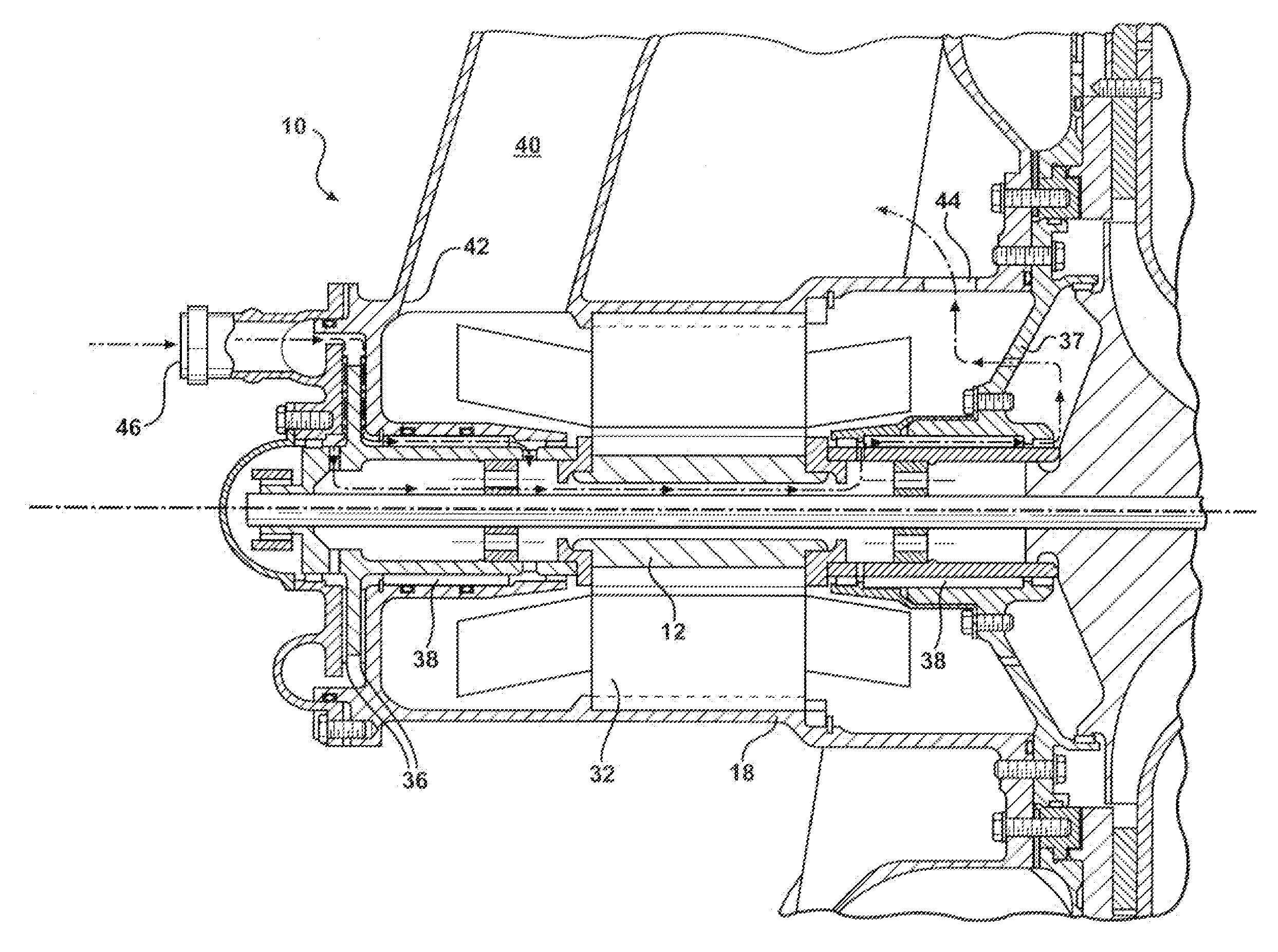
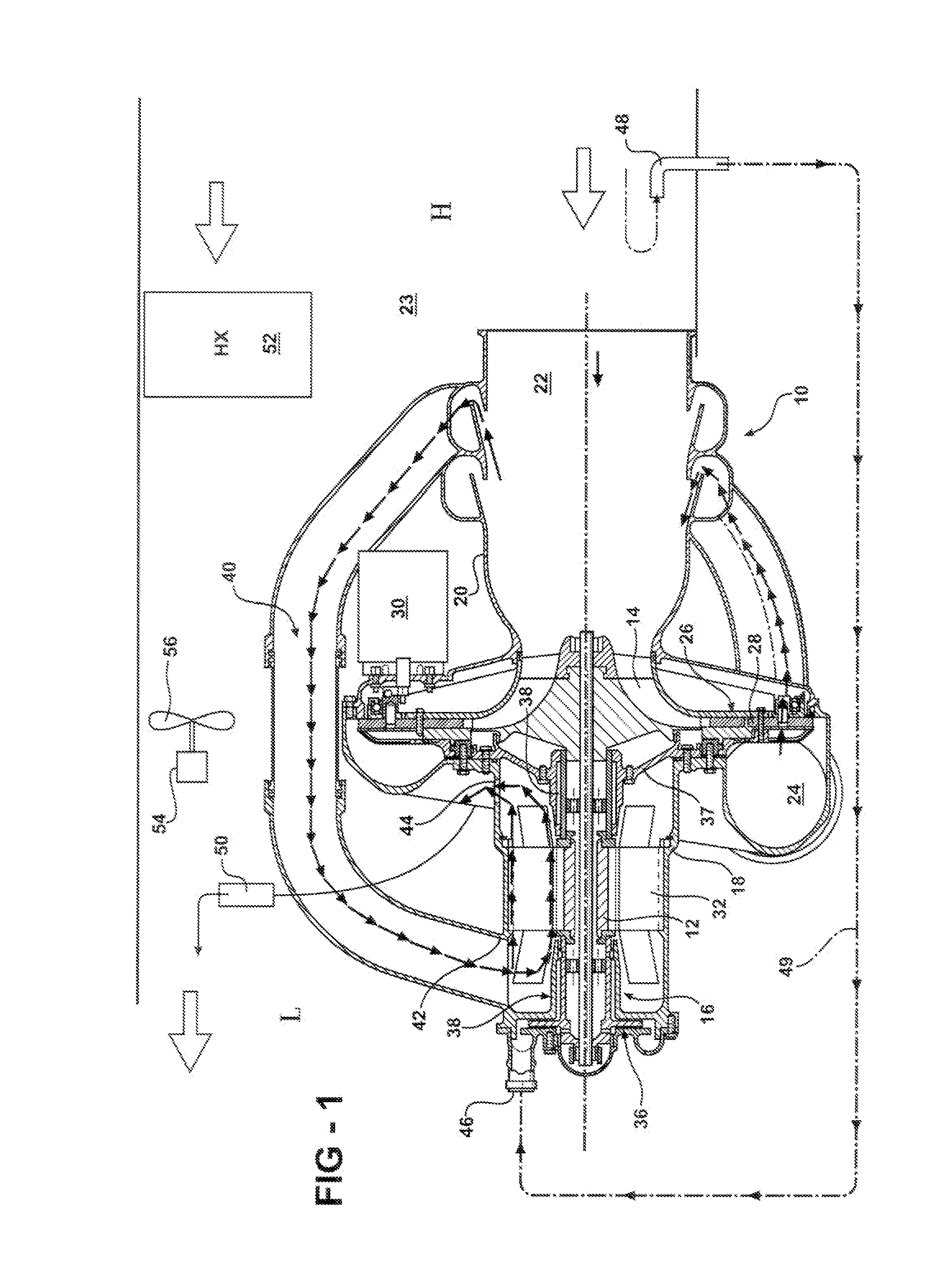
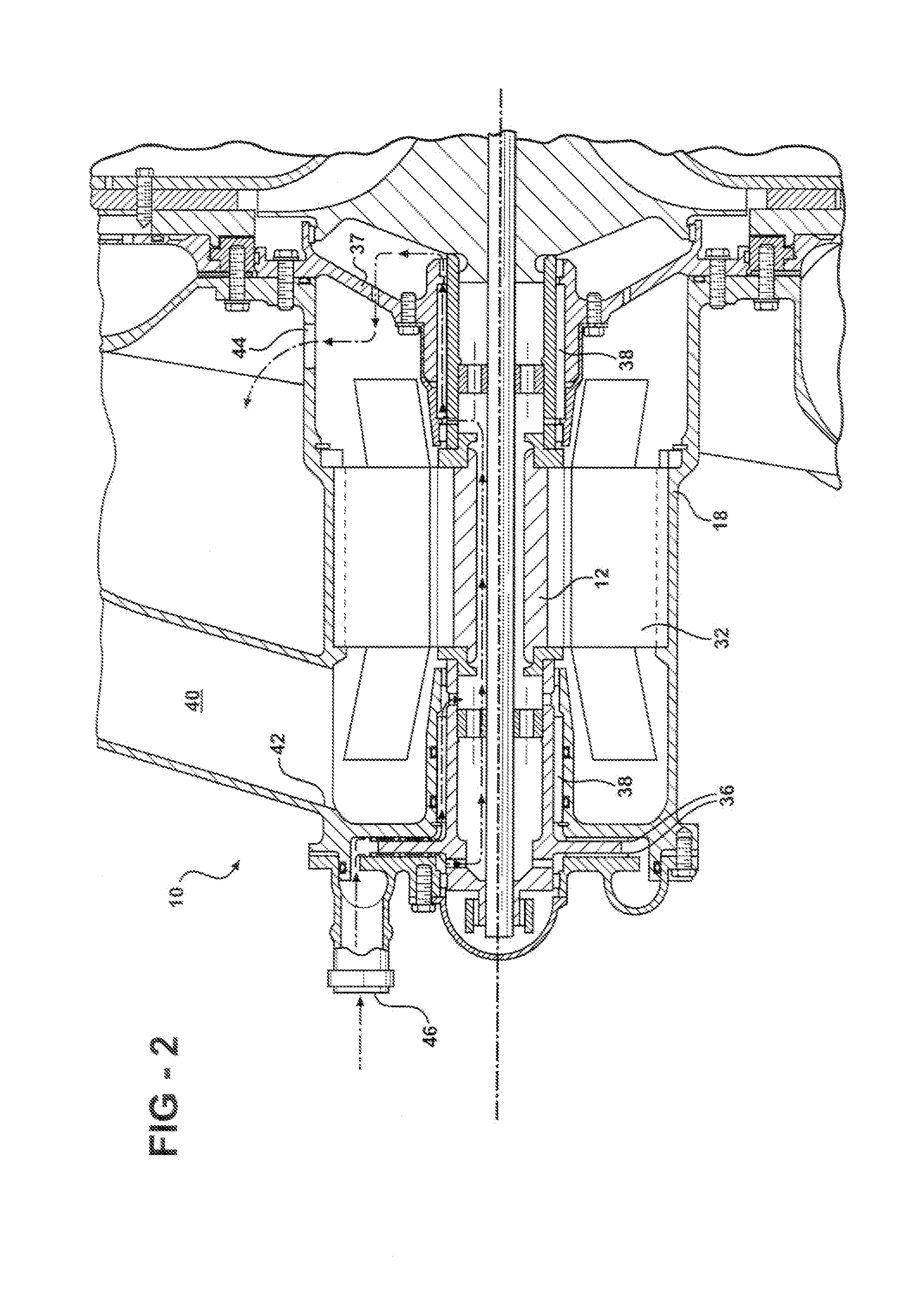
[0013]A compressed air unit 10 is shown in FIG. 1. The unit 10 includes a compressor rotor 12 supporting rotor blades 14. An electric motor 16 rotatably drives the compressor rotor 12.

[0014]The motor 16 is arranged in a motor housing 18, and a compressor housing 20 is secured to the motor housing 18. The compressor housing 20 provides a compressor inlet 22 for supplying air to the rotor blades 14. In the example shown, the compressor inlet 22 receives air from a ram air duct 23. The rotor blades 14 compress the air and provide compressed air to a compressor outlet 24.

[0015]A diffuser 26 is arranged between the rotor blades 14 and the compressor outlet 24 to vary the flow through the compressed air unit 10. The diffuser 26 includes vanes 28 that are moved by an actuator 30 to vary an inlet throat diameter provided by the vanes 28 thereby varying the flow through the compressed air unit 10.

[0016]The motor 16 includes a stator 32 arranged within the motor housing 18 that produces a mag...


PUM


Abstract

A motor includes a housing including separate motor and bearing cooling inlets. A motor is arranged within the housing and includes a stator and rotor assembly that is supported on air bearings. The motor cooling inlet is in fluid communication with the stator, and the bearing cooling inlet is in fluid communication with the air bearings. A vent is arranged in the housing and is common to the motor and bearing cooling inlets. The vent is in fluid communication with a low pressure side of a ram air duct. The bearing cooling duct is in fluid communication with a high pressure side of a ram air duct, such as through a reverse J-tube. A differential pressure between the high and low pressure sides moves cooling fluid from the bearing cooling inlet to the vent to cool the bearings.

Description

[0001]This applications claims priority to U.S. Provisional Patent Application Ser. No. 60 / 612,268, filed Sep. 22, 2004.BACKGROUND OF THE INVENTION[0002]This invention relates to an air bearing and motor cooling arrangement.[0003]Electric motors have several significant sources of heat that must be cooled to ensure desired operation of the motor. One significant source of heat is generated by the stator producing a magnetic field to drive a rotor assembly. Another significant source of heat is generated by bearings used to support the rotor assembly. In some high temperature motor applications, air bearings are used.[0004]The air bearings and stator of an electric motor have been cooled using two airflow paths that are separate from one another. That is, the airflow paths have separate inlets and separate outlets. As a result of using separate flow paths, the bearings are subject to different loads based upon the different pressures in the flow paths that are exerted on the rotor as...

Claims


Application Information

Patent Timeline
Patent Type & Authority Patents(United States)
IPC IPC(8): H02K9/00
CPCH02K7/083H02K7/14H02K9/06F04D25/06F04D29/5806
Inventor MCAULIFFE, CHRISTOPHERBEERS, CRAIG M.ZYWIAK, THOMAS
Owner HAMILTON SUNDSTRAND CORP
Why Eureka
Try Eureka