Piezomotor with a guide

a technology of piezomotors and guides, applied in piezoelectric/electrostrictive/magnetostrictive devices, piezoelectric/electrostriction/magnetostriction machines, electrical apparatus, etc., can solve the problems of complicated assembly and reliability, excessive cost for many applications, and motors that are too big, etc., to achieve the effect of stabilizing the position of the driven devi

a technology of piezomotors and guides, applied in piezoelectric/electrostrictive/magnetostrictive devices, piezoelectric/electrostriction/magnetostriction machines, electrical apparatus, etc., can solve the problems of complicated assembly and reliability, excessive cost for many applications, and motors that are too big, etc., to achieve the effect of stabilizing the position of the driven devi

US7342347B2Active Publication Date: 2008-03-11ELLIPTEC RESONANT ACTUATOR

Image

  • Piezomotor with a guide
  • Piezomotor with a guide
  • Piezomotor with a guide

Examples


Embodiment Construction

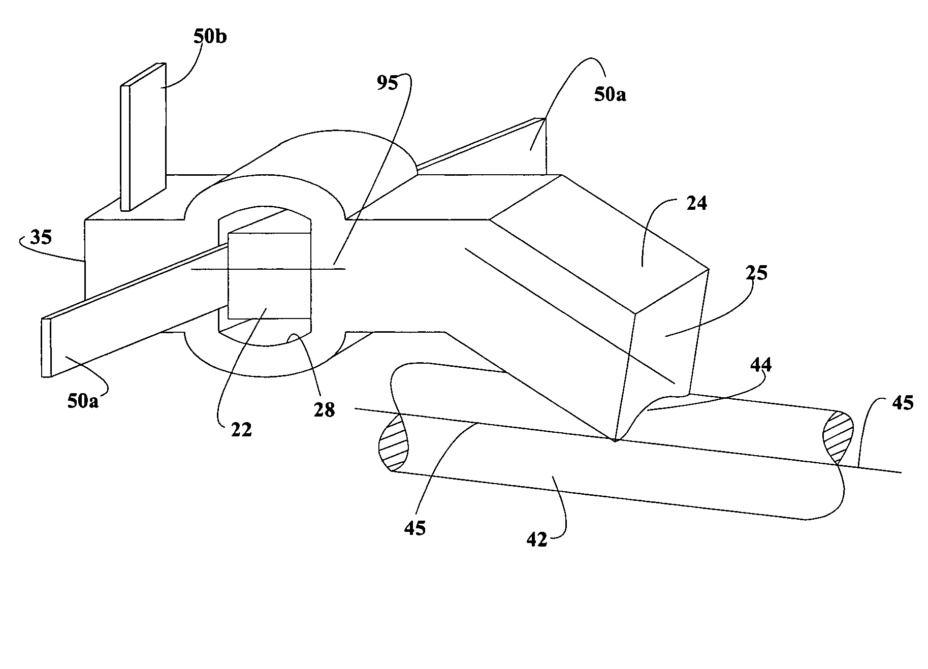
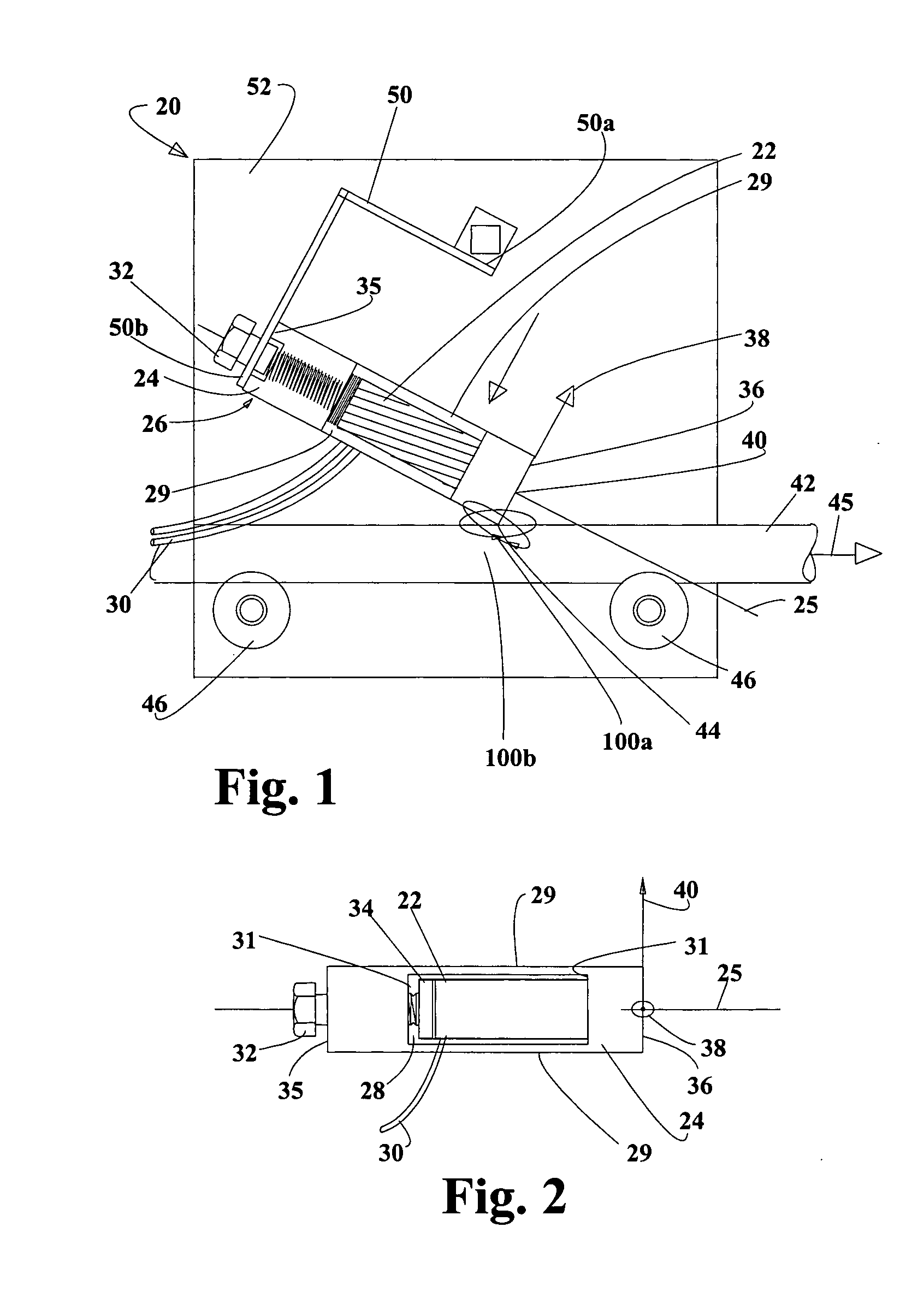
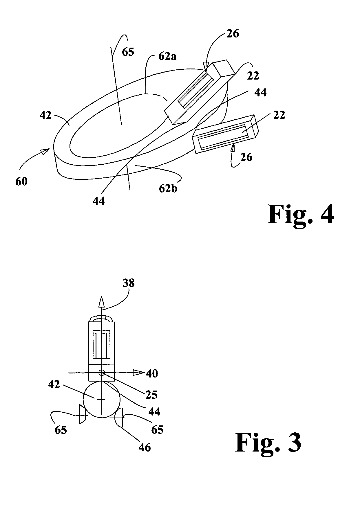
[0114]Several embodiments of the motor of this invention will be described, following which a number of theoretical and practical operational and design aspects of the motors are described. Referring to FIGS. 1-3, and as described in detail at various locations, the piezoelectric motor assembly 20 has an element that converts electrical energy into macroscopic mechanical motion. This is achieved by using a single electrical signal to generate at least two vibration motions at a predetermined location of a vibration element. The at least two vibration motions result in an elliptical motion at the predetermined location. The elliptical motion is selected to cause the vibrating element to engage a driven element during a time corresponding to at least a portion of travel in direction of a long axis of the ellipse, and to disengage or slide over the driven element during a time corresponding to travel in the opposite direction. A second, single frequency results in a second elliptical m...


PUM


Abstract

The present invention relates to a drive system comprising at least one motor with at least one vibration generator each as well as at least one resonator each and a device driven by said motor, wherein the resonator comprises a contact area that cooperates with the surface of the device in order to drive said device.

Description

CROSS-REFERENCE TO RELATED APPLICATIONS[0001]This application claims priority under 35 U.S.C. § 119(e) from U.S. patent application No. 60 / 191,876 filed Mar. 23, 2000 entitled “Electric Motor Using Vibration to Convert Electrical Energy Into Mechanical Motion” and listing inventors Bjoern Magnussen, Steve Schofield and Benjamin Hagemann; and from application No. 60 / 215,438 filed Jun. 30, 2000, application No. 60 / 215,686 filed Jun. 30, 2000, application No. 60 / 231,001 filed Sep. 8, 2000, and application No. 60 / 236,005 filed Sep. 27, 2000, each entitled “Electrical Motor Using Vibration to Convert Electrical Energy Into Mechanical Motion” and listing inventors Bjoern Magnussen, Benjamin Hagemann and Peter Varadi; and also claims priority under 35 U.S.C. § 120 from application Ser. No. 09 / 801,194 filed Mar. 8, 2001, and application Ser. No. 10 / 691,362 filed Mar. 22, 2003, each titled “Vibratory Motors and Methods of Making and Using Same” and listing inventors Bjoern Magnussen, Peter V...

Claims


Application Information

Patent Timeline
11 Mar 2008
Publication
US7342347B2
IPC
H02N2/00; H02N2/02; H10N30/20
CPC
H02N2/0065; H02N2/026; H02N2/103
Inventors
MAGNUSSEN, BJOERN; HAGEMANN, BENJAMIN