Fluted anode with minimal density gradients and capacitor comprising same

a technology of density gradient and fluted anode, which is applied in the direction of liquid electrolytic capacitor, fixed capacitor, fixed capacitor details, etc., can solve the problems of surface burnishing, reduced current flow resistance of the anode body, and reduced capacitor performance, so as to improve the electrical properties of the capacitor, improve the consistency of solid electrolyte impregnation, and improve the effect of capacitor performan

Active Publication Date: 2008-03-11
KEMET ELECTRONICS CORP
View PDF30 Cites 33 Cited by
  • Summary
  • Abstract
  • Description
  • Claims
  • Application Information

AI Technical Summary

Benefits of technology

[0015]It is another object of the present invention to provide an anode with improved consistency in solid electrolyte impregnation.
[0016]A particular feature of the present invention is the ability to further improve electrical properties of capacitors, and circuits containing capacitors, without increases in ESR or inductance, while still maintaining high capacitance per unit volume.

Problems solved by technology

Although the lead wire(s) can be attached to the anode body, for example by welding to the top of the body, imbedding the lead wire(s) in the anode body reduces the resistance for current to flow.
Both increases result in higher equivalent series resistance—ESR—which diminishes the performance of the capacitor.
Alternatively, the anode is formed by axially pressing the powder parallel to the anode wire which causes surface burnishing which also inhibits external coating coverage.
Yet another problem associated with fluted anodes is insufficient conduction between the anode and the cathode lead frame.
As shown, the cavity of deep, or wide, flutes causes difficulty when attempting to attach the anode over the entire surface of the cathode lead frame.
As efforts to further improve the electrical characteristics of capacitors proceeds the ESR limitations caused by the poor surface contact rises to the fore as a limiting parameter in capacitor design.

Method used


Image

  • Fluted anode with minimal density gradients and capacitor comprising same
  • Fluted anode with minimal density gradients and capacitor comprising same
  • Fluted anode with minimal density gradients and capacitor comprising same

Examples


Embodiment Construction

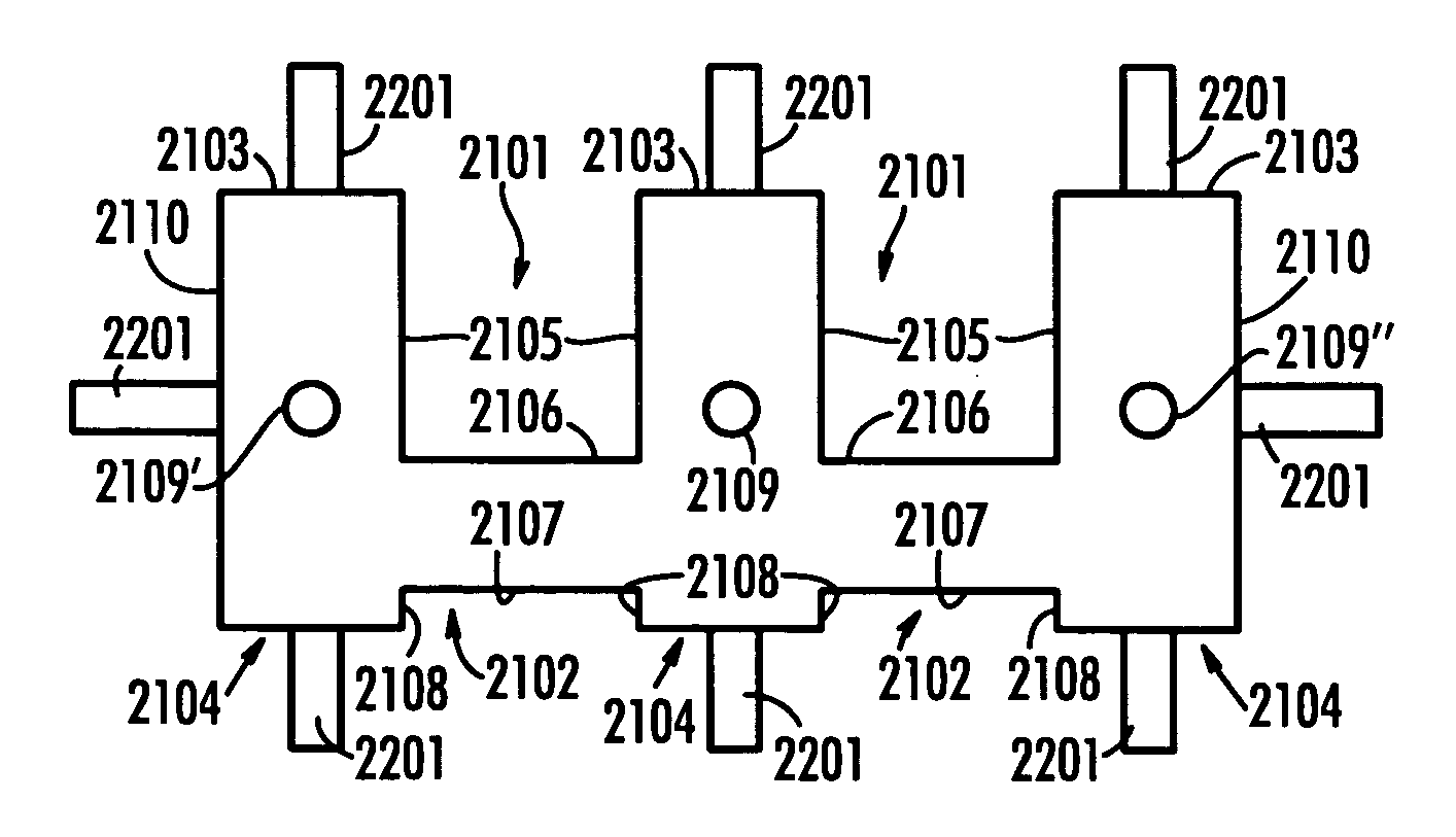
[0065]An improved anode for use in a capacitor is detailed wherein the anode has lower deviations in density, reduced resistance, better contact with the lead frame, and improved electrical characteristics of the capacitor resulting from the improvements in the anode. The anode has multiple anode lead wires. The cathode comprises a conductive polymer.

[0066]The present invention will be described with reference to the various figures forming an integral part of the specification. Throughout the various drawings similar elements will be numbered accordingly.

[0067]Resistance of a capacitor has been considered by those in the art to be primarily due to the resistance of the cathode and semiconductor layers with minimal contribution from the anode. This understanding is based on the large differences between the resistance of the anode, which is about 13.1×10⁻⁶ Ω / cm for tantalum, as compared to about 1 Ω / cm for MnO2 and about 0.01 Ω / cm for conductive polymers. For example, it is estimate...


PUM


Abstract

An anode with an anode body with a first side and a second side opposite to said first side, multiple anode wires and a conductive polymer cathode.

Description

CROSS-REFERENCE TO RELATED APPLICATIONS[0001]The present application is a continuation-in-part of U.S. patent application Ser. No. 11 / 199,626 filed Aug. 9, 2005 , now U.S. Pat. No. 7,116,548 issued Oct. 3, 2006 , which is in-turn a continuation-in-part application of U.S. patent applcation Ser. No. 10 / 830,616 filed Apr. 23, 2004 which is abandoned. This application is related to U.S. patent application Ser. No. 10 / 730,736 filed Dec. 8, 2003 , now U.S. Pat. No. 7,207,103 issued Apr. 24, 2007, which is pending and incorporated herein by reference.FIELD OF THE INVENTION[0002]The present invention is directed to an improved anode with offset, or unequal, flutes and minimal density gradients, capacitors comprising the improved anode and the synergism of such anodes with conductive polymeric cathodes. More particularly the present invention is directed to an improved anode comprising flutes and multiple wires and anodes with a conductive polymer cathode.BACKGROUND OF THE INVENTION[0003]Th...

Claims


Application Information

Patent Timeline
Patent Type & Authority Patents(United States)
IPC IPC(8): H01G9/04H01G4/228
CPCH01G9/012H01G9/042H01G9/14H01G9/15
Inventor HAHN, RANDY S.QIU, YONGJIAN
Owner KEMET ELECTRONICS CORP
Why Eureka
Try Eureka