Device for surveying the pressure of fluids housed in tanks or flowing through ducts

a technology for fluids and ducts, which is applied in the field of devices capable of surveying the pressure of fluids, can solve the problems of tire leakage, device defects, and small internal dimensions of devices to be used for surveying, and achieve the effect of shortening the total length of devices

Inactive Publication Date: 2008-03-18
SISTEC SRL
View PDF9 Cites 5 Cited by
  • Summary
  • Abstract
  • Description
  • Claims
  • Application Information

AI Technical Summary

Benefits of technology

[0031]The main advantages offered by the invention are that the exceeding of the threshold values of relative pressure is sensed by means of a plurality of mechanical sensors that simultaneously commute and emit a signal that depends on the instantaneous value of relative pressure of the fluid to be surveyed. The fluid is housed in a proper measuring chamber inside the device. Therefore, the emission of the signal occurs independently on the movement or the change of the geometrical configuration of other parts of the device. The sensors are capable of operating without electrical feeding, since the commutation is assured by the elastic energy absorbed by the sensors stressed by external forces, or by means of application of pressure stresses of the fluid acting on suitable surfaces.

Problems solved by technology

In addition, the device has very small dimensions and mass to be used for surveying the internal pressure of a tire.
However, the device presents some defects:
If the device in which, in case of pressure lower than the threshold value, a suitable plunger moves of some millimeters in order to allow the closing of the inflation valve, has no reliable seal, the tire continues to leak until its complete deflation.
But, if the plunger, because of excessive damages, frictions or deviations with respect to the external envelope, does not sufficiently move, the signal is not emitted.
This lamina is difficult to be realised particularly in mass productions of devices requiring close geometrical and operating tolerances.
For this reason, small deformations of the gasket compromise the precision of its geometry, in particular after an extended use of the device.
Said reactions are indeterminate during the assembly of the device and irregularly change in time because of the permanent deformations of the gaskets.

Method used


Image

  • Device for surveying the pressure of fluids housed in tanks or flowing through ducts
  • Device for surveying the pressure of fluids housed in tanks or flowing through ducts
  • Device for surveying the pressure of fluids housed in tanks or flowing through ducts

Examples


first embodiment

[0134]The functioning of the device 100 is explained with reference to a first embodiment shown in FIG. 3. The other embodiments will be explained later.

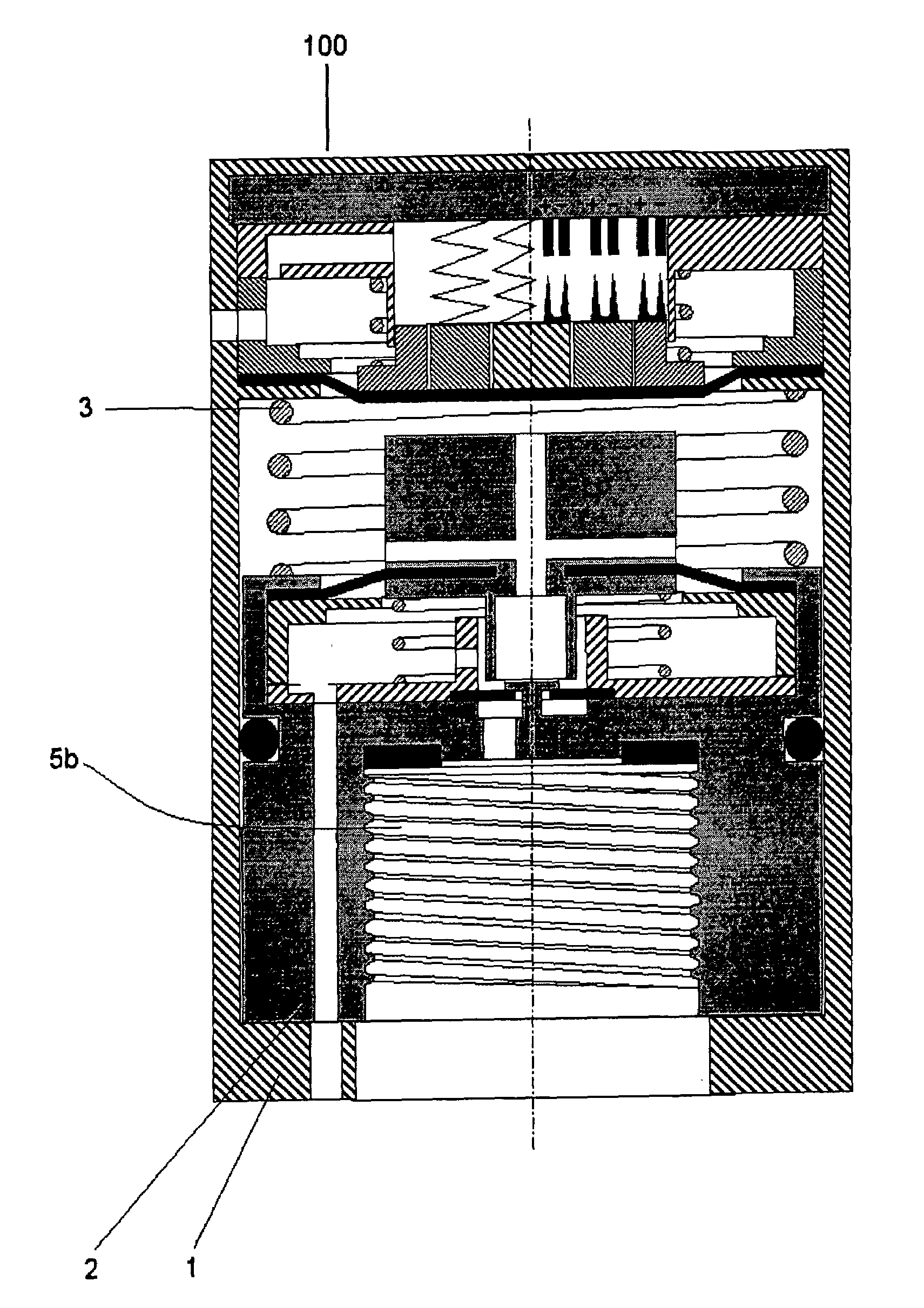
[0135]In FIG. 3 the device 100 according to the present invention is illustrated still being in the sale packaging. An axial symmetric envelope 1 forms the external coating of the device 100. The envelope 1 is kept in the position distal with respect to a connecting body 2 by a counter spring 3.

[0136]The envelope 1 axially slides with respect to the body 2 in order to allow the commutation of the device 100 from a non-active to an active condition. The commutation of the device 100 is due to the action of an external force F.

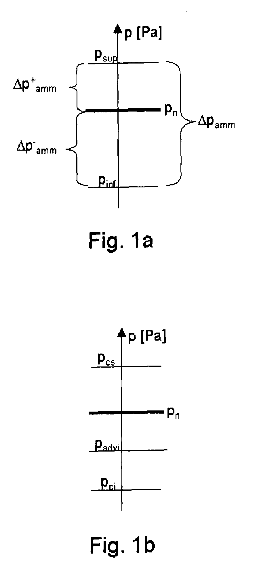
[0137]The device 100 keeps its active condition if the relative pressure of the fluid is higher than a prefixed first threshold value Pci.

[0138]The envelope 1 is connected to the body 2 by means of a prismatic coupling (not shown in FIG. 3), allowing the envelope 1 to transmit a torque to the body 2.

[0139]In FIG...

second embodiment

[0264]FIG. 19 shows the device 100 providing the removal of the counter spring 3 interposed between the body 2 and the supporting basis 35 integral with the envelope 1, for reducing the full axial dimensions of the device 100.

[0265]In the non-active condition of the device 100, the edge 21a of the hollow rod 21 of the rigid member 22 is not in contact with the self-closing diaphragm 15. The measuring chamber 30 is connected to the environment through the ducts 24, 24a, 24b, the cavity 23, the chamber 25 and the ducts 26a, 26b, 26c. The surface 16 of the self-closing diaphragm 15 is in contact with the edge 18 of the end 19 at the end of the pin 20.

[0266]In the non-active condition of the device 100, also in case the fluid is in the chamber 14, it will cannot invade the cavity 23 and the chamber 25 because of the hermetic seal between the surface 16 of the self-closing diaphragm 15 and the edge 18 of the end 19. Therefore, in this embodiment, in the non-active condition the envelope ...

third embodiment

[0271]FIG. 21 shows the device 100 allowing to keep on providing the advantage consisting of the shortening of the total length of the device 100 and, at the same time, to maintain the counter spring 3 interposed between the body 2 and the supporting basis 35 integral with the envelope 1. In order to keep the same radial dimensions of the first deforming diaphragm, the required space to house the counter spring 3 is found in an interspace 58 which is obtained by increasing the radial dimensions of the envelope 1.

[0272]A device 100 is realised presenting all the features of the first disclosed embodiment but with a total shorter length and a longer radial dimension.


PUM

PropertyMeasurementUnit
pressureaaaaaaaaaa
external forceaaaaaaaaaa
relative pressureaaaaaaaaaa

Abstract

An apparatus for surveying the pressure of fluids housed in tanks or flowing through ducts comprises a device (100), an envelope (1) with axial symmetry which forms the external covering of the device (100), said envelope (1) being kept in distal position with respect to a connecting body (2) by a counter spring (3); the envelope (1) axially slides with respect to the body (2) to allow the commutation of the apparatus (100) from a non-active to an active condition; the commutation of the device (100) is due to an external force (F).

Description

[0001]This is a nationalization of PCT / IT2004 / 000669 filed 2 Dec. 2004 and published in English.BACKGROUND OF THE INVENTION[0002]The present invention relates to a device capable surveying the pressure of fluids housed in tanks or flowing through ducts. The device according to the invention is used in the industry, the sanitary services, the transports and in all those civil or military systems in which the pressure must remain within pre-established values or threshold values to avoid the decay or the operating stop of the system comprising said tanks or ducts.[0003]Some examples of systems using one or more devices according to the present invention are as follows:[0004]a) air compressed braking systems for road or rail vehicles;[0005]b) static balancing circuits for power-operated machines and robots;[0006]c) pneumatic circuits, in general, for power-operated machines, automatic machine tools and the like;[0007]d) tires for road or rail vehicles or aeroplanes;[0008]e) delivering ...

Claims


Application Information

Patent Timeline
Patent Type & Authority Patents(United States)
IPC IPC(8): G01L17/00B60C23/00B60C23/04G01L7/00G01L7/10
CPCB60C23/0408B60C23/0496G01L7/00B60C23/00G01L7/04
Inventor PELLICCIARI, MARCELLO
Owner SISTEC SRL
Why Eureka
Try Eureka