Exhaust emission control device and method for internal combustion engine, and engine control unit

an emission control device and internal combustion engine technology, applied in electrical control, exhaust treatment electric control, separation processes, etc., can solve the problems of increased exhaust emissions, increased exhaust emissions, and excessive supply of reducing agents, so as to reduce the amount of heat generated by oxidation reaction, the degree of catalyst degradation is higher, and the storage capacity and oxidation capability of the catalyst is reduced.

Inactive Publication Date: 2012-02-21
HONDA MOTOR CO LTD
View PDF7 Cites 5 Cited by
  • Summary
  • Abstract
  • Description
  • Claims
  • Application Information

AI Technical Summary

Benefits of technology

[0014]With the configuration of this exhaust emission control device, the reducing agent supply amount indicative of the amount of reducing agent supplied to the NOx catalyst is calculated, and when the calculated reducing agent supply amount exceeds a threshold value, the reduction control is terminated. Further, as the estimated degree of degradation of the catalyst is higher, the threshold value is corrected to be smaller. Accordingly, as the degree of degradation of the catalyst is higher, i.e. as the amount of reducing agent consumed in the catalyst is smaller, it becomes easier for the reducing agent supply amount to exceed the threshold value, which makes shorter the time period over which the reduction control should be executed. This makes it possible to supply a just enough amount of reducing agent to the NOx catalyst, and thereby obtain the aforementioned advantageous effects.

Problems solved by technology

This increases exhaust emissions due to insufficient reduction of NOx.
Inversely, when the amount of reducing agent consumed in the three-way catalyst is small, the timing for termination of the rich spike becomes late than it should be, which causes an excessive supply of reducing agent.
This causes excess amounts of CO and HC to be generated, resulting in increased exhaust emissions and degraded fuel economy.

Method used


Image

  • Exhaust emission control device and method for internal combustion engine, and engine control unit
  • Exhaust emission control device and method for internal combustion engine, and engine control unit
  • Exhaust emission control device and method for internal combustion engine, and engine control unit

Examples


first embodiment

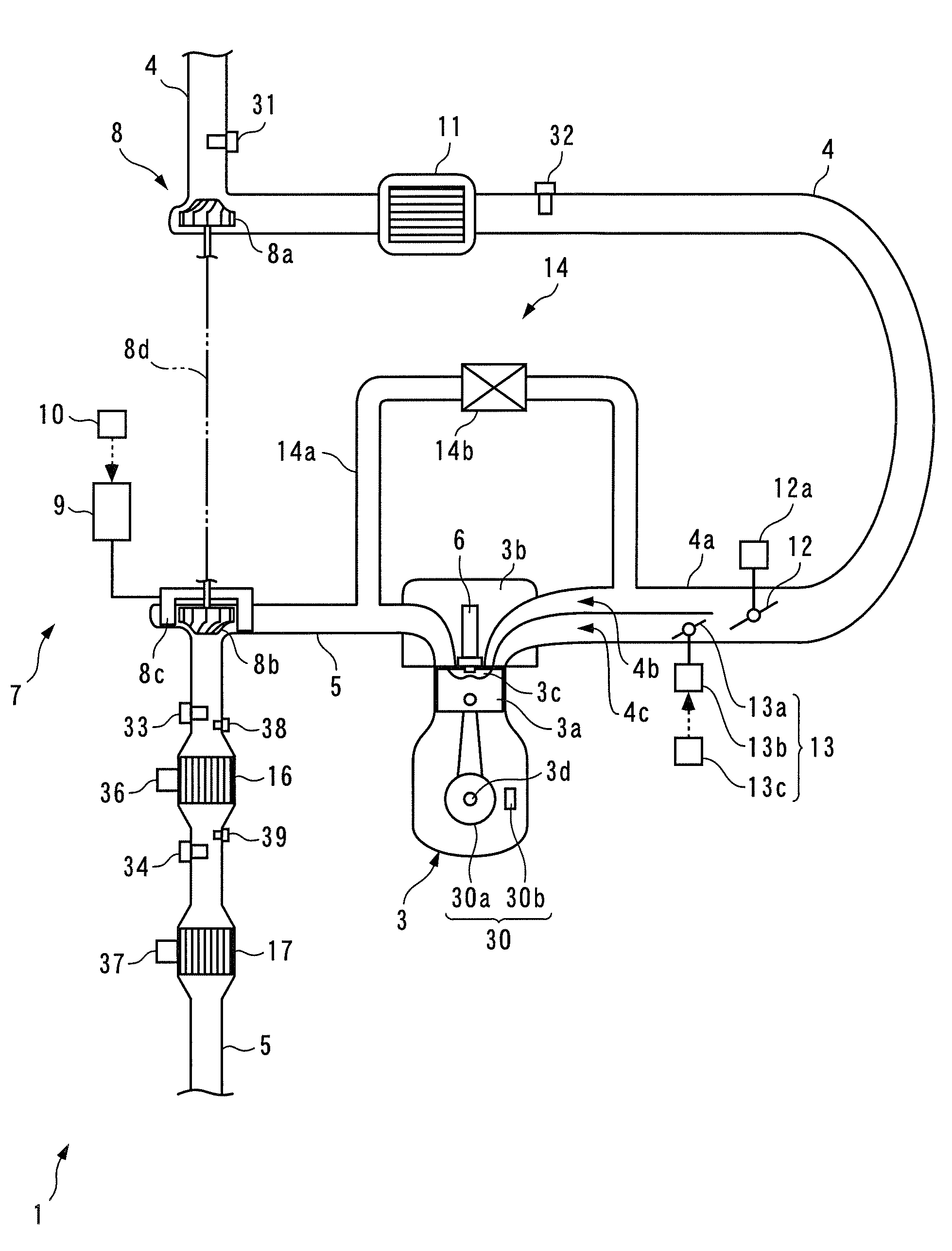
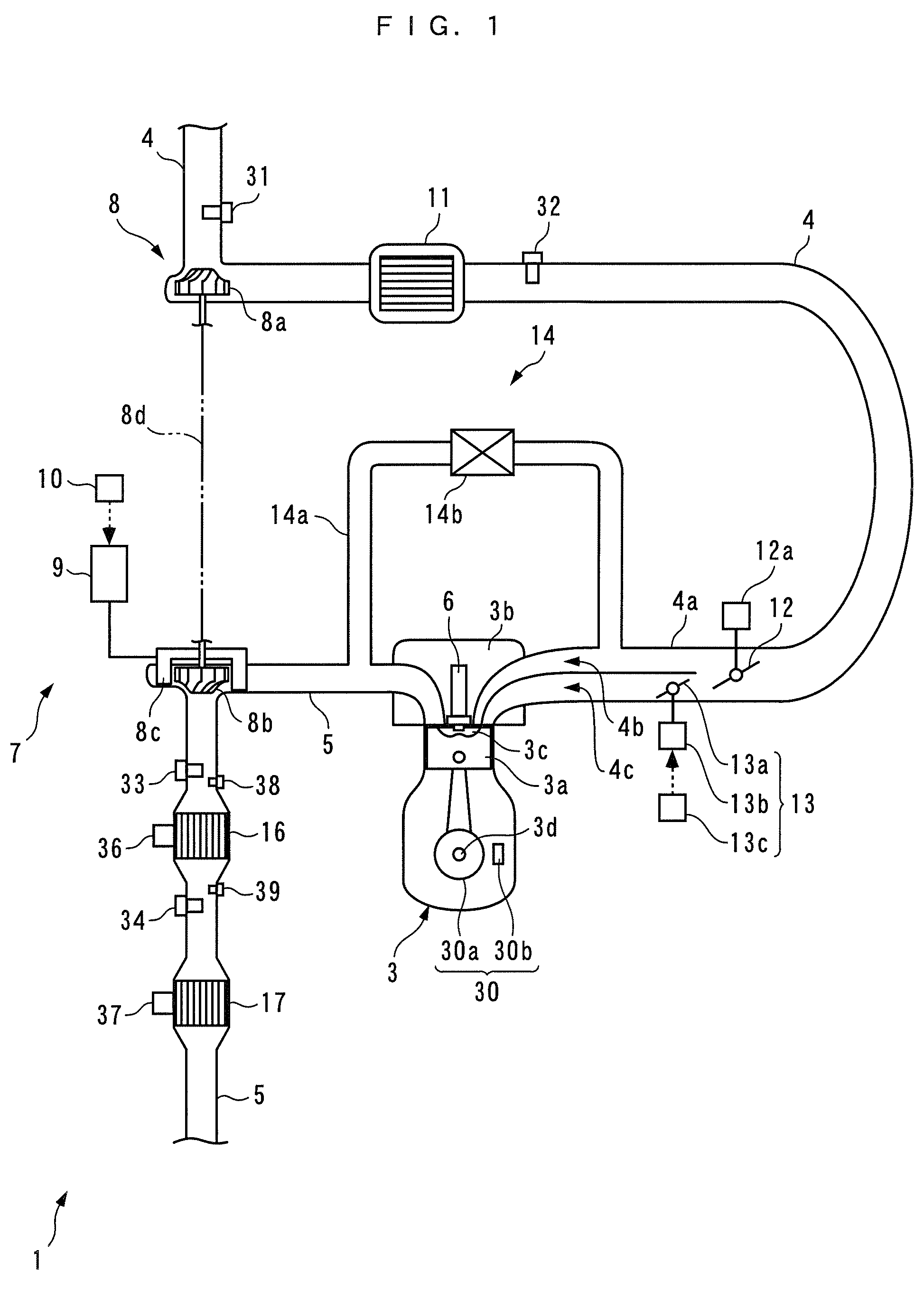
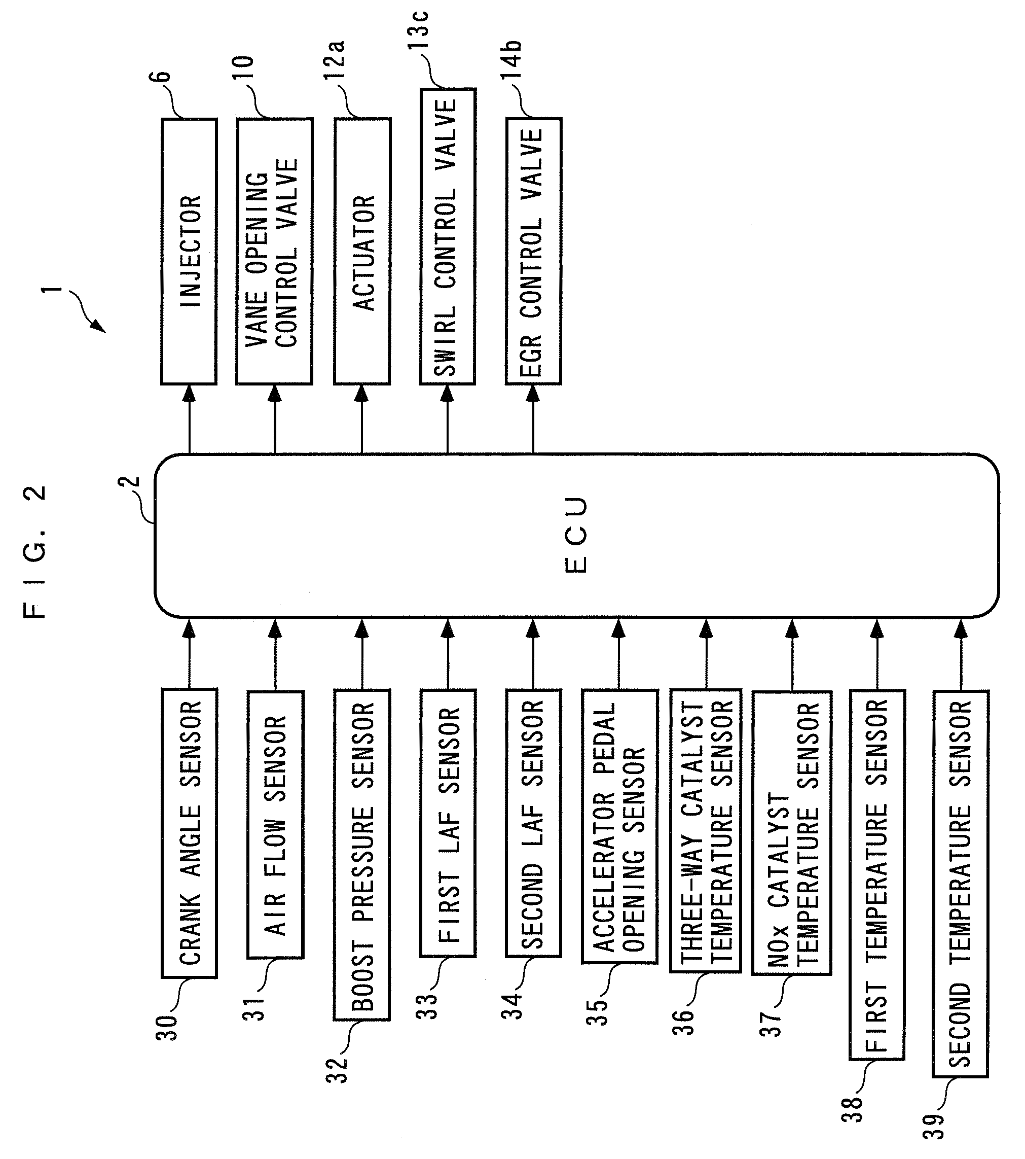
[0097]FIG. 9 shows the process for estimating degradation of the three-way catalyst 16, which is executed by the exhaust emission control device according to the According to this process, from the mutual relationship between the upstream temperature TTWC1 and the downstream temperature TTWC2 of the three-way catalyst 16 detected by the first and second temperature sensor 38 and 39, the degradation degree DEGRA of the three-way catalyst is estimated, and according to the estimated degradation degree DEGRA, the first degradation-dependent correction coefficient KDEGRA1 to be applied to the reducing agent amount reference value S_QDAREF in the step 9 in FIG. 3 is calculated.

[0098]In this process, first, it is determined whether or not an estimation completion flag F_DONE is equal to 1 (step 50). If the answer to this question is affirmative (YES), i.e. if the estimation of the degradation degree of the three-way catalyst 16 is completed, the present process is immediately terminated....

second embodiment

[0113]FIG. 16 shows a process for estimating degradation of the three-way catalyst 16 according to the present invention. According to this process, the air-fuel ratio of exhaust gases at a location downstream of the three-way catalyst 16 is estimated, and from the relationship between the estimated second estimated air-fuel ratio AF2_EST and the second actual air-fuel ratio AF2_ACT detected by the second LAF 34, the degradation degree DEGRA of the three-way catalyst 16 is estimated.

[0114]In this process, first, it is determined whether or not the degradation estimation completion flag F_DONE is equal to 1 (step 70). If the answer to this question is affirmative (YES), i.e. if the estimation of the degradation degree of the three-way catalyst 16 has already been completed, the present process is immediately terminated.

[0115]On the other hand, if the answer to the question of the step 70 is negative (NO), it is determined whether or not the rich spike flag F_RICH is equal to 1 (step ...


PUM


Abstract

An exhaust emission control device for an internal combustion engine which is capable of supplying a just enough amount of reducing agent to a NOx catalyst while causing the consumption amount of reducing agent dependent on the degradation degree of an upstream catalyst to be reflected thereon. A NOx catalyst is disposed at a location downstream of a catalyst having an oxidation function for purifying exhaust gases, for trapping NOx contained in exhaust gases in an oxidizing atmosphere, and reducing the trapped NOx in a reducing atmosphere to thereby purify the trapped NOx. Exhaust gases flowing into the NOx catalyst are controlled to the reducing atmosphere, by supplying reducing agent to an upstream side of the catalyst. The degradation degree of the catalyst is estimated, and a time period over which the reduction control should be executed is corrected according to the estimated degradation degree.

Description

CROSS REFERENCE TO RELATED APPLICATION[0001]This application claims the priority of Japanese Application No. 317855 / 2006, filed Nov. 24, 2006 the entire specification, claims and drawings of which are incorporated herewith by reference.BACKGROUND OF THE INVENTION[0002]1. Field of the Invention[0003]The present invention relates to an exhaust emission control device and method for an internal combustion engine, and an engine control unit, for purifying i.e. decreasing exhaust emissions by temporarily trapping NOx contained in exhaust gases discharged from the engine and performing reduction of the trapped NOx.[0004]2. Description of the Related Art[0005]Conventionally, there has been disclosed an exhaust emission control device for an internal combustion engine, e.g. in Japanese Laid-Open Patent Publication (Kokai) No. 2006-207487. This internal combustion engine is a diesel engine in which a three-way catalyst and a NOx catalyst are disposed in an exhaust pipe thereof from the upstr...

Claims


Application Information

Patent Timeline
Patent Type & Authority Patents(United States)
IPC IPC(8): F01N3/00
CPCB01D53/9409B01D53/9495F01N3/0871F01N3/206F01N9/00F01N11/00F01N13/009F02D41/0275F02B37/00F02D2200/0811Y02T10/47Y02T10/24F01N2550/02Y02T10/12Y02T10/40
Inventor MORITA, TOMOKOSUZUKI, NORIOKONOMOTO, TAKASHI
Owner HONDA MOTOR CO LTD
Why Eureka
Try Eureka