Device for surveying the pressure of fluids housed in tanks or flowing through ducts.
- Summary
- Abstract
- Description
- Claims
- Application Information
AI Technical Summary
Benefits of technology
Problems solved by technology
Method used
Image
Examples
first embodiment
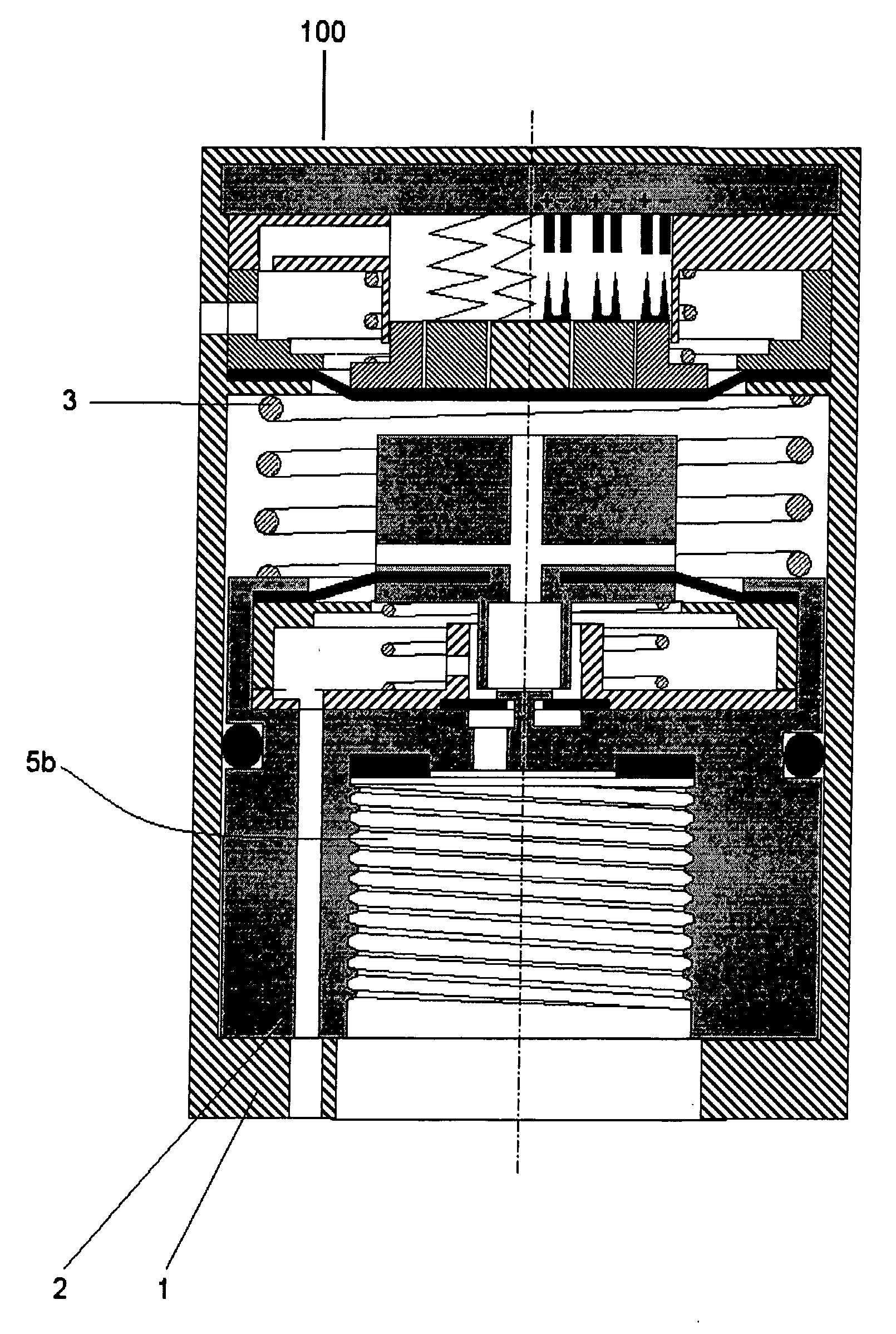
[0136] The functioning of the device 100 is explained with reference to a first embodiment shown in FIG. 3. The other embodiments will be explained later.
[0137] In FIG. 3 the device 100 according to the present invention is illustrated still being in the sale packaging. An axial symmetric envelope 1 forms the external coating of the device 100. The envelope 1 is kept in the position distal with respect to a connecting body 2 by a counter spring 3.
[0138] The envelope 1 axially slides with respect to the body 2 in order to allow the commutation of the device 100 from a non-active to an active condition. The commutation of the device 100 is due to the action of an external force F.
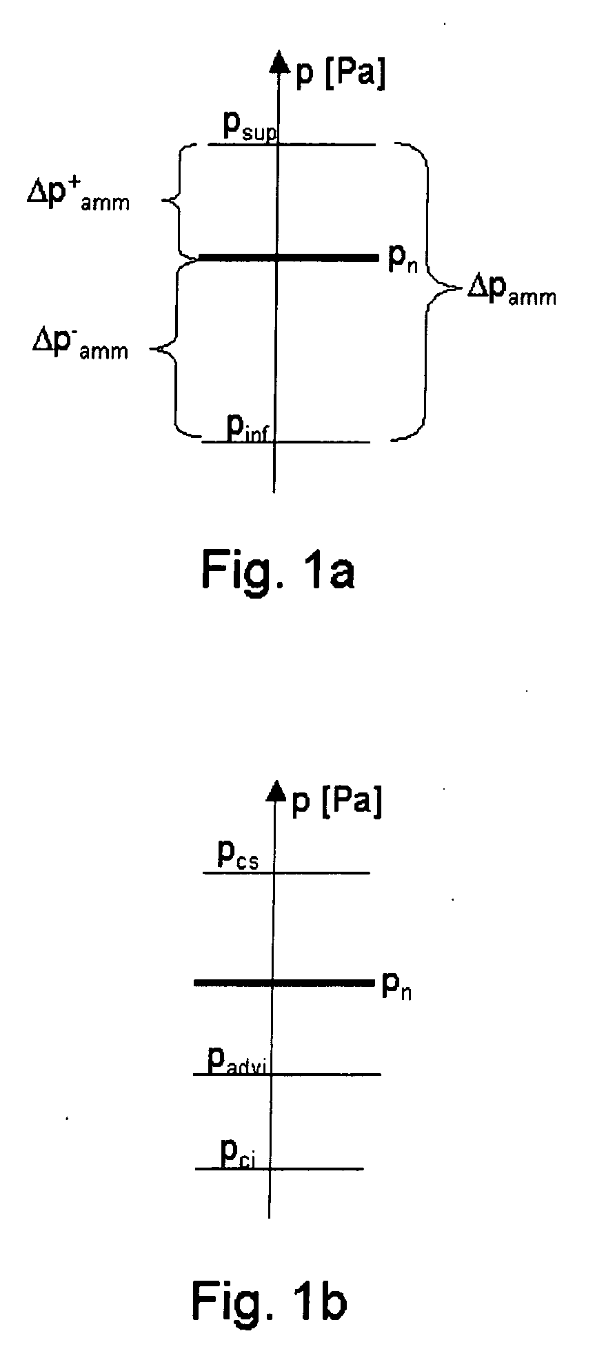
[0139] The device 100 keeps its active condition if the relative pressure of the fluid is higher than a prefixed first threshold value Pci.
[0140] The envelope 1 is connected to the body 2 by means of a prismatic coupling (not shown in FIG. 3), allowing the envelope 1 to transmit a torque to the body 2.
[01...
second embodiment
[0272]FIG. 19 shows the device 100 providing the removal of the counter spring 3 interposed between the body 2 and the supporting basis 35 integral with the envelope 1, for reducing the full axial dimensions of the device 100.
[0273] In the non-active condition of the device 100, the edge 21a of the hollow rod 21 of the rigid member 22 is not in contact with the self-closing diaphragm 15. The measuring chamber 30 is connected to the environment through the ducts 24, 24a, 24b, the cavity 23, the chamber 25 and the ducts 26a, 26b, 26c. The surface 16 of the self-closing diaphragm 15 is in contact with the edge 18 of the end 19 at the end of the pin 20.
[0274] In the non-active condition of the device 100, also in case the fluid is in the chamber 14, it will cannot invade the cavity 23 and the chamber 25 because of the hermetic seal between the surface 16 of the self-closing diaphragm 15 and the edge 18 of the end 19.
[0275] Therefore, in this embodiment, in the non-active condition the...
third embodiment
[0280]FIG. 21 shows the device 100 allowing to keep on providing the advantage consisting of the shortening of the total length of the device 100 and, at the same time, to maintain the counter spring 3 interposed between the body 2 and the supporting basis 35 integral with the envelope 1. In order to keep the same radial dimensions of the first deforming diaphragm, the required space to house the counter spring 3 is found in an interspace 58 which is obtained by increasing the radial dimensions of the envelope 1.
[0281] A device 100 is realised presenting all the features of the first disclosed embodiment but with a total shorter length and a longer radial dimension.
PUM
 Abstract
Description
Claims
Application Information
 - R&D
- Intellectual Property
- Life Sciences
- Materials
- Tech Scout
- Unparalleled Data Quality
- Higher Quality Content
- 60% Fewer Hallucinations
Browse by: Latest US Patents, China's latest patents, Technical Efficacy Thesaurus, Application Domain, Technology Topic, Popular Technical Reports.
© 2025 PatSnap. All rights reserved.Legal|Privacy policy|Modern Slavery Act Transparency Statement|Sitemap|About US| Contact US: help@patsnap.com


