Apparatus for abnormal diagnosis of variable valve timing mechanism

a timing mechanism and variable valve technology, applied in valve control, machine/engine, process and machine control, etc., can solve the problems of phase difference inevitably occurring, abnormality of adjustable valve mechanism detected, and extremely large amount of labor required for experiments to validate the setting of reference, etc., to achieve the effect of high accuracy and versatility

Inactive Publication Date: 2008-03-18
TOYOTA JIDOSHA KK
View PDF17 Cites 9 Cited by
  • Summary
  • Abstract
  • Description
  • Claims
  • Application Information

AI Technical Summary

Benefits of technology

[0006]The object of the invention is thus to solve the problems discussed above and to provide a versatile and highly accurate abnormality diagnosis technique that diagnoses an abnormality of an adjustable valve mechanism.

Problems solved by technology

For example, when the target phase angle is set at a higher speed than the response of the adjustable valve mechanism, a phase difference inevitably arises even in the normal state of the adjustable valve mechanism.
Namely the abnormality of the adjustable valve mechanism is mistakenly detected.
An extremely large amount of labor is then required for experiments to validate the settings of the reference value.
It is accordingly difficult to apply the reference values to another type of the vehicle.

Method used


Image

  • Apparatus for abnormal diagnosis of variable valve timing mechanism
  • Apparatus for abnormal diagnosis of variable valve timing mechanism
  • Apparatus for abnormal diagnosis of variable valve timing mechanism

Examples


example 1

(1) MODIFIED EXAMPLE 1

[0074]Computation of the phase angle based on the physical model may include some error, and accumulation of such errors may lower the accuracy of abnormality diagnosis. One possible modification thus calibrates the theoretical value computed according to the physical model, based on the result of the abnormality diagnosis and the driving conditions of the vehicle.

[0075]FIG. 7 is a flowchart showing a modified abnormality diagnosis routine, which includes calibration of the computation result according to the physical model and is executed in place of the flowchart of FIG. 6. The CPU of the ECU first determines whether the revolution speed of the crankshaft measured by the crankshaft sensor is not lower than a preset value R (step S100). When the observed revolution speed of the crankshaft is not lower than the preset value R (step S100: Yes), the CPU receives an input control signal (step S110), and computes the theoretical value of the phase angle of the inta...

example 2

(2) MODIFIED EXAMPLE 2

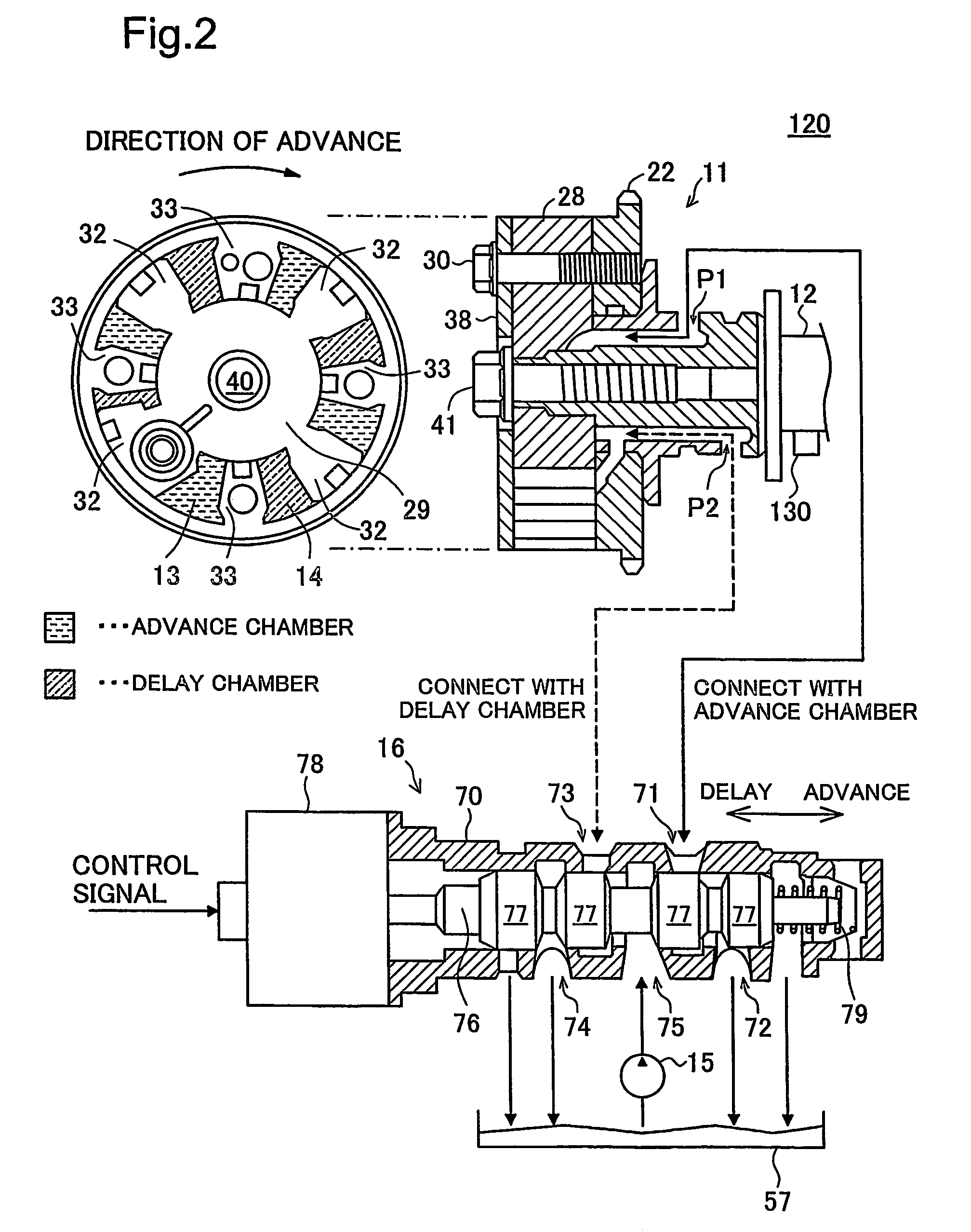
[0080]FIG. 8 shows a modified example of the physical model. This modified physical model is created on the assumption that oil leaks through clearances between the spool 76 and the casing 70. The clearances are given as orifices 5 and 6. The flow rate of oil through these clearances is calculated according to Equation (5) given above with the area of each clearance set to the opening area A of the orifice. The clearance in the piston 200 is also given as an orifice 7. Reflection of the potential oil leakage on the computation according to the physical model further enhances the accuracy of abnormality diagnosis.

example 3

(3) MODIFIED EXAMPLE 3

[0081]The abnormality diagnosis routine shown in the flowchart of FIG. 6 or the modified abnormality diagnosis routine shown in the flowchart of FIG. 7 determines the abnormal state of the adjustable valve mechanism 120, based on the difference between the theoretical value and the observed value of the phase angle of the intake cam shaft 12. One possible modification may determine the abnormal state of the adjustable valve mechanism 120, based on a difference between a theoretical value and an observed value of a variation in phase angle per unit time or based on a difference between an expected phase angle after elapse of a predetermined time period and an observed phase angle actually measured after elapse of the predetermined time period. For example, the procedure compares the expected phase angle to 30 degrees after elapse of 3 seconds computed according to the physical model with the observed phase angle actually measured after elapse of 3 seconds and de...


PUM


Abstract

An abnormality diagnosis system 100 includes a VVT controller 110, an adjustable valve mechanism 120, a cam angle sensor 130, a model computation module 140, an abnormality detection module 150, and an alarm lamp 160. The adjusable valve mechanism 120 advances or delays a phase angle of an intake cam shaft relative to a crankshaft, thereby varying an open-close timing of a valve. The model computation module 140 computes a physical behavior of the adjustable valve mechanism 120 according to a physical model, in response to a control signal input from the VVT controller 110. The abnormality detection module 150 determines whether the adjustable valve mechanism 120 is abnormal or normal, based on a difference between a theoretical value of phase angle calculated according to the physical model and an observed value of phase angle measured with the cam angle sensor 130. The arrangement of the invention ensures highly accurate abnormality diagnosis of the adjustable valve mechanism 120.

Description

TECHNICAL FIELD[0001]The present invention relates to a technique of diagnosing an abnormality in an adjustable valve mechanism.BACKGROUND ART[0002]An adjustable valve mechanism is often applied to an internal combustion engine mounted on a vehicle for the enhanced output, the reduced fuel consumption, and the reduced emission. The adjustable valve mechanism varies a valve characteristic, such as an open-close timing or an opening-closing lift quantity of a valve.[0003]Diverse techniques have been proposed to diagnose an abnormality of this adjustable valve mechanism. For example, the technique disclosed in Japanese Patent Laid-Open Gazettes No. 2002-161789 and No. 2001-303999 given below calculates a difference between a target phase angle of a cam shaft and an actual phase angle measured by a cam angle sensor and compares the calculated difference with a preset threshold value to determine abnormality or normality of the adjustable valve mechanism. The technique disclosed in Japan...

Claims


Application Information

Patent Timeline
Patent Type & Authority Patents(United States)
IPC IPC(8): F01L1/34
CPCF01L1/022F01L1/34F02D41/221F01L2001/34453F01L2710/006F01L2800/00Y02T10/40F01L2001/34423
Inventor SOEJIMA, SHINICHI
Owner TOYOTA JIDOSHA KK
Why Eureka
Try Eureka