Reversible space plane

a space plane and wing technology, applied in the field of reversible space planes, can solve the problems of cataclysmic loss of columbia, and become a daunting behemoth that is very costly to assemble and launch

Inactive Publication Date: 2008-03-18
JANEKE CHARL E
View PDF17 Cites 26 Cited by
  • Summary
  • Abstract
  • Description
  • Claims
  • Application Information

AI Technical Summary

Problems solved by technology

In addition to the mass of the payload, problems with the tiled heat shield led to the catastrophic loss of the Columbia.
Because of the need to clear the atmosphere relatively quickly and reliance on boosters, the NASA space shuttle evolved into a daunting behemoth that is very costly to assemble and launch.

Method used


Image

  • Reversible space plane
  • Reversible space plane
  • Reversible space plane

Examples


Embodiment Construction

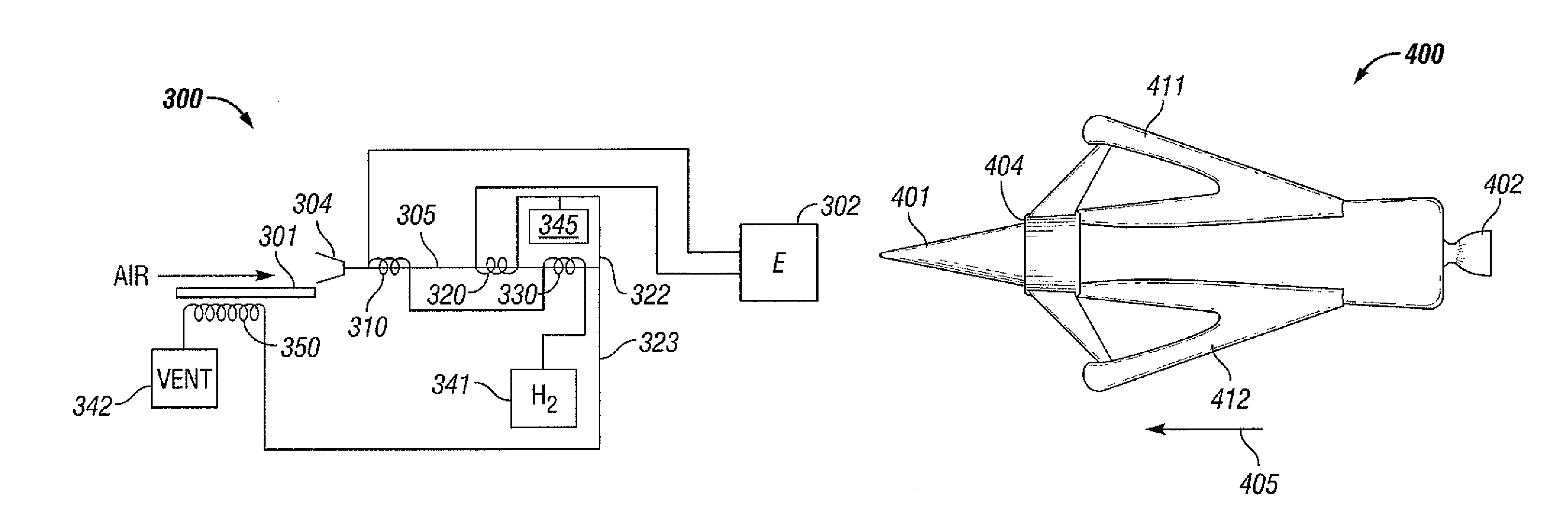
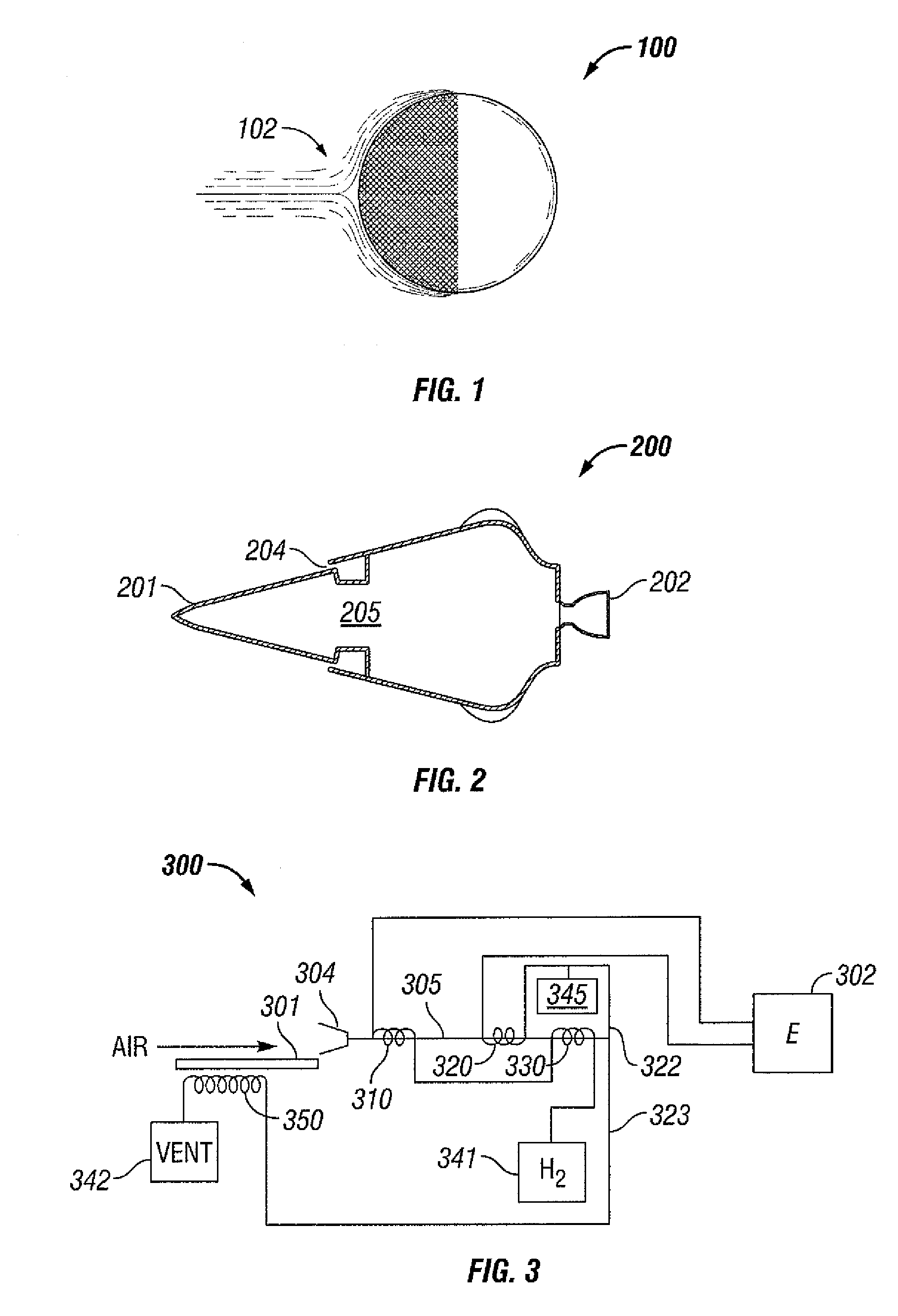
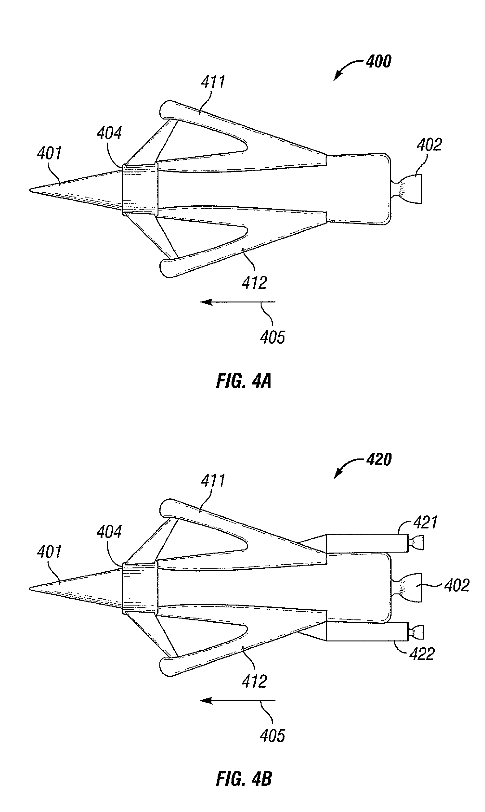
[0018]An aerospace plane in accordance with one or more embodiments of the invention may be a reversible aerospace plane. The aerospace plane may include an air liquefaction system that enable the aerospace plane to travel at hypersonic velocities in the atmosphere with reduced drag. When operated in the reverse direction, the aerospace plane may exhibit a larger drag so that the kinetic energy from an orbital velocity may be dissipated at a higher altitude and over a longer time period that conventional vehicles.

[0019]FIG. 1 shows the ideal situation of a sphere 100 moving at hypersonic velocity through the atmosphere. The surface 102 of the front half of the sphere 100 is an ideal condenser that will condense the incident air to a liquid upon contact with the surface 102. In this ideal model, instead of creating a shockwave in the atmosphere, the sphere 100 condenses the air, thereby creating a partial vacuum in front of the sphere 100. The effect of this condensation of air is to...


PUM


Abstract

A reversible aerospace plane includes an air intake at a first end of the aerospace plane, at least one heat exchanger disposed in the aerospace plane, an engine at a second end of the aerospace plane, wherein the aerospace plane is configured to accelerate in a first direction and configured to glide and land in a second direction, wherein the second direction is substantially in a reverse direction from the first direction.

Description

CROSS-REFERENCE TO RELATED APPLICATIONS[0001]This application claims the priority from U.S. Provisional Application No. 60 / 538,417 filed on Jan. 23, 2004. This Provisional Application is incorporated by reference in its entirety.BACKGROUND OF INVENTION[0002]The loss of the space shuttle Columbia in 2003 highlights a need for a safer reusable single-stage-to-orbit (“SSTO”). The Columbia included a payload during re-entry, which was not typical for such re-entries. In addition to the mass of the payload, problems with the tiled heat shield led to the catastrophic loss of the Columbia. Due to the shuttle's relatively small footprint, structural weight, and rapid decent into the atmosphere, it dissipates most of the kinetic energy of orbital velocity in the denser atmosphere, relying exclusively on the heat shield to remain intact. Because of the need to clear the atmosphere relatively quickly and reliance on boosters, the NASA space shuttle evolved into a daunting behemoth that is very...

Claims


Application Information

Patent Timeline
Patent Type & Authority Patents(United States)
IPC IPC(8): B64G1/00B64G1/14F02K9/42
CPCB64G1/14F02K9/42
Inventor JANEKE, CHARL E.
Owner JANEKE CHARL E
Why Eureka
Try Eureka