Socket for led light source and lighting system using the socket

a technology of led light source and socket, which is applied in the direction of lighting support devices, lighting and heating apparatus, and connection of coupling devices, etc. it can solve the problems of long life, leds may not produce the desired illuminance, and the amount of heat generated in leds is inevitably large, so as to reduce the number of components and reduce the manufacturing cost.

Active Publication Date: 2008-03-18
PANASONIC CORP
View PDF26 Cites 189 Cited by
  • Summary
  • Abstract
  • Description
  • Claims
  • Application Information

AI Technical Summary

Benefits of technology

[0018]In view of the above problems, the object of the present invention is to provide an LED light-source socket suitable for practical use that enables stable driving while effectively releasing heat generated in each LED during driving, and also to provide a lighting system having the socket without disfigurement of the lighting system.

Problems solved by technology

Unlike typical conventional light sources, LEDs do not use a filament and therefore have a long life.
The amount of heat generated in the LEDs is inevitably large.
This means that some LEDs may fail to produce a desired illuminance under high-temperature conditions.
If these LEDs having different temperature characteristics are, combined for use as a light source, controlling of color emitted from the light source becomes difficult.
When a card-type LED module is inserted into a socket, heat generated from each LED included in the card-type LED module is trapped in the vicinity of the socket.
Such significant concentration of heat in one area is problematic.
Another problem to be solved is a difficulty in the replacement operation of the LED card 1000.
This removing operation can be difficult for the user because the lighting system 2000 is often placed in an area of limited accessibility such as on the ceiling.
In particular, if the user tries to remove the LED card 1000 by uncomfortable body positioning such as stretching his or her arms or bending his or her body, the side parts 1000a and 1000b of the LED card 1000 may get stuck in the grooves 2021, thereby increasing the burden on the user involved in the replacement operation.
In this case, however, the projected part may drastically degrade the appearance of the lighting system.
However, simply employing such a constructing may further complicate the replacement operation of the LED card 1000.

Method used


Image

  • Socket for led light source and lighting system using the socket
  • Socket for led light source and lighting system using the socket
  • Socket for led light source and lighting system using the socket

Examples


first embodiment

1. First Embodiment

1.1 Construction of the Socket for LED Light Source

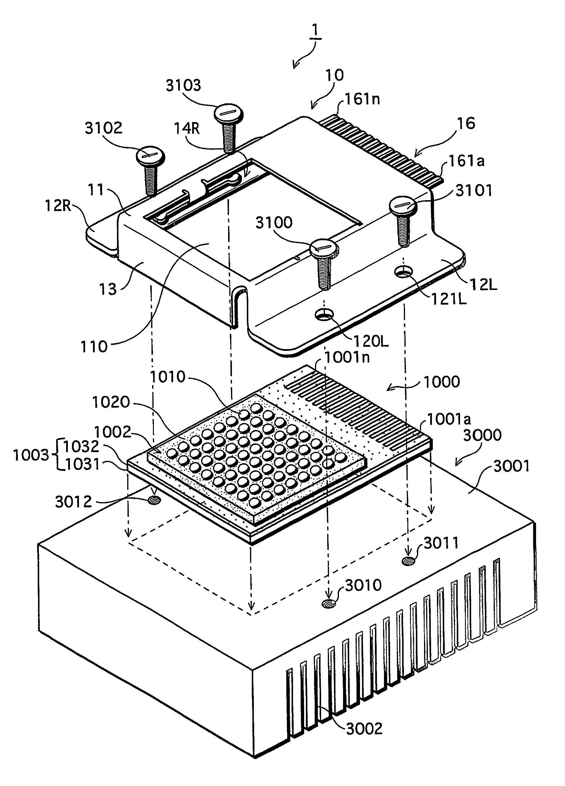
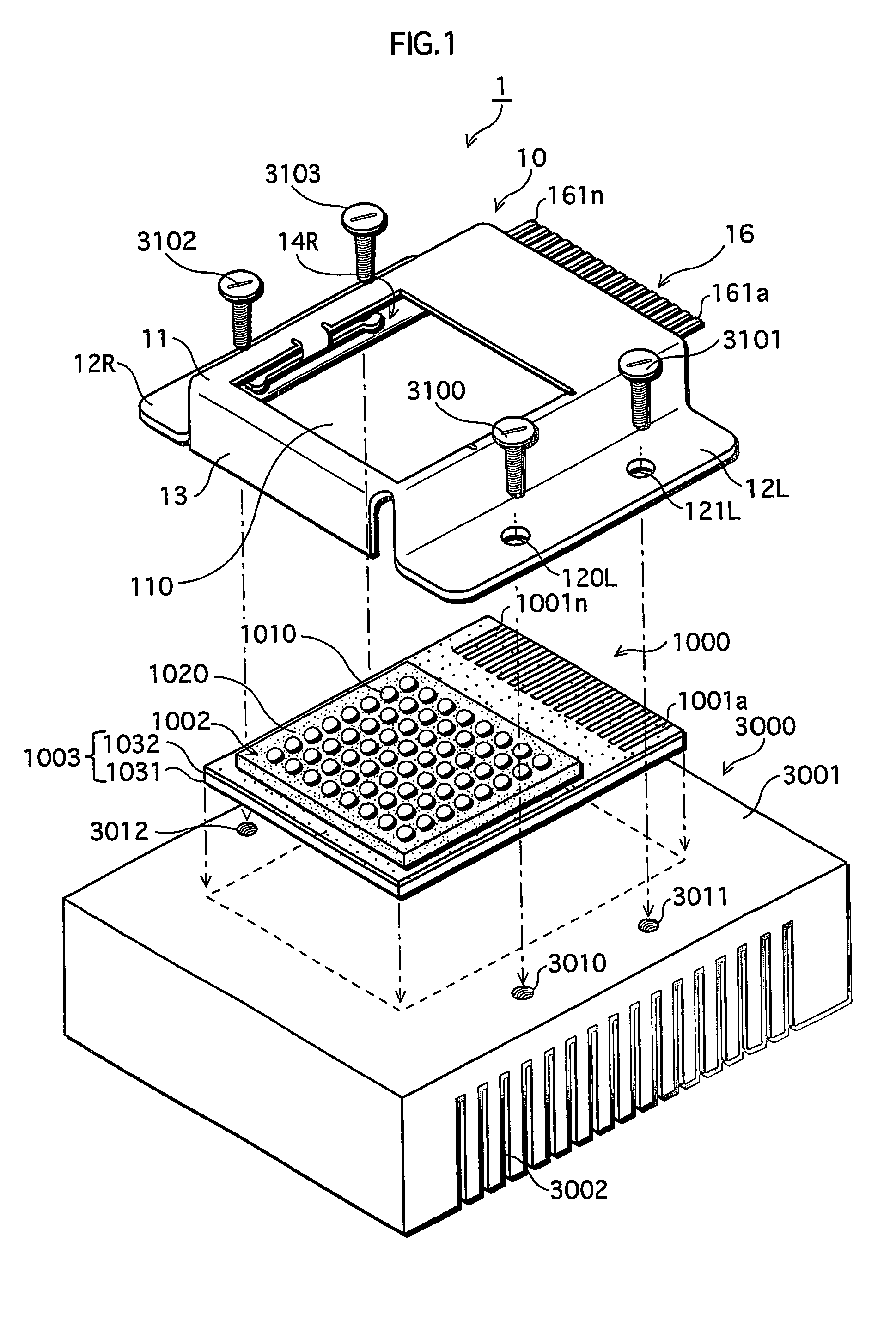
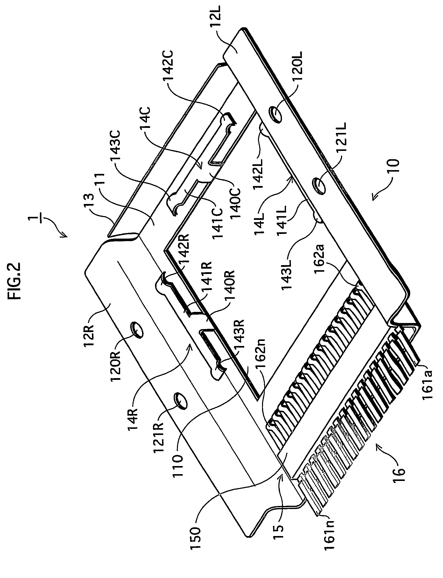
[0062]FIG. 1 shows the construction of a socket 1 designed for an LED light source, relating to a first embodiment of the present invention. FIG. 2 shows the construction of a back side of the socket 1. FIGS. 15A to 15C show the construction of an LED card.

[0063]FIG. 1 shows the constructions of the socket 1 designed for an LED light source, a card-type LED module 1000 as one example of the LED light source (hereafter simply “LED card 1000”), and a heat sink 3000.

[0064]As shown in the figure, the heat sink 3000 is made from a rectangular solid metal member (here, aluminum member) with good heat-releasing properties. In one main surface of the heat sink 3000, a large number of fins 3002 are formed like the teeth of a comb, to enhance the heat-releasing effect. On another main surface 3001 of the heat sink 3000 (the upper surface in the figure), screw holes 3010 to 3013 (3013 not shown) for screws 3100 to 3103 used ...

second embodiment

2. Second Embodiment

[0076]FIG. 4 shows the construction of an LED light-source socket relating to a second embodiment of the present invention.

[0077]The socket 2 relating to the second embodiment shown in the figure is, as its characteristic, formed by processing an aluminum plate with high heat conductivity. The socket 2 has a construction where an external terminal unit 27 having the same construction as that in the first embodiment is attached to a frame member 21 in which an opening unit 201 is formed by punching or shaving off the corresponding part of the aluminum plate. The lower surface of the frame member 21 is subjected to such patterning to form steps that correspond to the shape of the LED card 1000, so that the LED card 1000 can be securely covered and held by the frame member 21. The second embodiment differs from the first embodiment in that the frame member 21 of the socket 2 presses the peripheral parts of the light source unit 1002. It should be noted here that a h...

third embodiment

3. Third Embodiment

[0079]FIG. 5 shows the construction of an LED light-source socket relating to a third embodiment of the present invention.

[0080]As shown in the figure, the shape of the socket of the present invention should not be limited to the rectangular shape employed in the first and second embodiments. The socket 3 relating to the third embodiment is composed of a circular frame member 31 in which an opening unit 301 is formed. Screw holes 301 to 303 are formed in the frame member 31.

[0081]The socket 3 having this construction relating to the third embodiment can produce substantially the same effect as the effect described in the second embodiment. To be specific, the LED card 1000 can be positioned right below the frame member 31. Using the screw holes 301 to 303 shown in the figure, the socket 3 in which the LED card 1000 is set can be fixed to the heat sink. Here, the light source unit 1002 of the LED card 1000 is exposed through the opening unit 201, with its periphera...


PUM


Abstract

A socket fixed to a heat sink holds a card-type LED module formed by integrating LED elements. The socket (6) includes: a frame structure for holding the LED module (1000) with its light source unit exposed through the frame opening; and a pressing member positioned around the opening for pressing the back surface of the LED module against the heat sink (2122). The socket may include a structure including a lower member (61) placed on a heat sink and an upper frame member (62) holding the LED module with its light source unit (1002) exposed through the frame opening. The upper member supported by the lower member via a hinge can open / close, and includes a pressing unit pressing the LED module set in the open state, against the lower member (61). The lower member (61) includes, in its main part, a lock unit (63) directly or indirectly lock the upper member (62) when the upper member is closed.

Description

TECHNICAL FIELD[0001]The present invention relates to a socket designed for an LED light source for lighting applications, and in particular relates to a socket suitable for a card-type LED module formed by mounting LED bare chips on a metal substrate, and to a lighting system using the socket.BACKGROUND ART[0002]LED (light emitting diode) light sources are now calling attentions as next-generation new light sources. Unlike typical conventional light sources, LEDs do not use a filament and therefore have a long life. Further, LEDs have a number of advantageous features such as compact manufacturing due to its extremely small and thin dimensions. A wide range of lighting applications are expected for LEDs as light sources, with its favorable features including reduced limitations on the mounting position.[0003]As one example, Japanese Laid-Open Patent Application No. S62-8403 discloses a lighting system that uses an LED light source formed by arranging linear lead frames in parallel,...

Claims


Application Information

Patent Timeline
Patent Type & Authority Patents(United States)
IPC IPC(8): H01R33/00F21V21/00F21V29/00F21K99/00F21V17/10F21V19/00F21V19/04F21V23/06
CPCF21K9/00F21V19/0045F21V19/0055F21V29/004F21V29/763F21V19/045F21K9/30F21V29/73F21V17/107F21V23/06F21Y2105/001Y10S362/80F21Y2101/02F21K9/20F21Y2105/10F21Y2115/10F21V19/04H01L33/483
Inventor MATSUI, NOBUYUKISHIMIZU, MASANORIMATSUO, KAZUHISAKAWABE, EIJI
Owner PANASONIC CORP
Why Eureka
Try Eureka