
Moving obstacle detecting device

a detection device and moving object technology, applied in the field of moving obstacle detection devices, can solve the problem of not being able to detect moving objects that are too large to be contained in a single small region, and achieve the effect of high degree of precision

Inactive Publication Date: 2008-03-18
NISSAN MOTOR CO LTD
View PDF9 Cites 24 Cited by
  • Summary
  • Abstract
  • Description
  • Claims
  • Application Information

AI Technical Summary

Benefits of technology

[0005]The present invention was conceived in order to resolve this problem in the prior art and its object is to provide a moving obstacle detecting device that can detect the existence of a moving obstacle with a higher degree of precision.

Problems solved by technology

Since the device disclosed in the aforementioned Patent Document 1 does not execute the previously described image processing with respect to the entire image, i.e., since it executes the processing separately for each small region, it is not capable of detecting moving objects that are too large to be contained in a single small region.

Method used


Image

  • Moving obstacle detecting device
  • Moving obstacle detecting device
  • Moving obstacle detecting device

Examples


Embodiment Construction

[0014]An embodiment of the present invention will now be described with reference to the drawings. Parts that are identical or similar are indicated in the drawings with the same reference numerals and duplicate descriptions thereof are omitted for the sake of brevity.

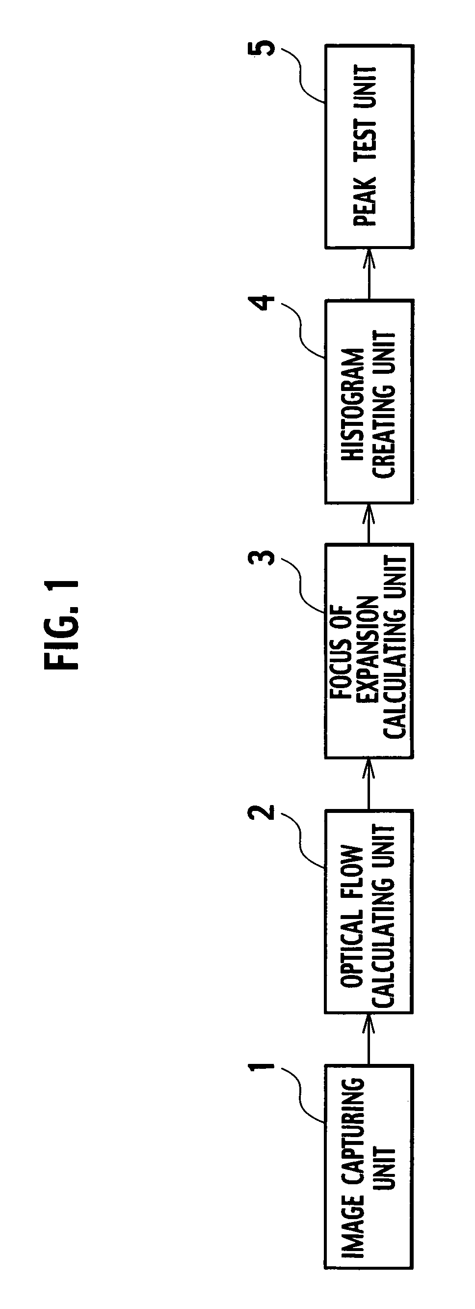
[0015]FIG. 1 is a block diagram showing the constituent features of a moving obstacle detecting device of an embodiment in accordance with the present invention. This embodiment exemplifies a case in which the moving body on which the device is installed is a vehicle and the moving obstacle is another vehicle or a pedestrian in the vicinity of the vehicle. The embodiment merely presents an example and the present invention is not limited to a vehicle as the moving body and a vehicle or pedestrian as the moving obstacle. As shown in FIG. 1, the moving obstacle detecting device includes the following: a camera (image capturing unit) 1 configured and arranged to capture an image of the surroundings of a vehicle; an optica...


PUM


Abstract

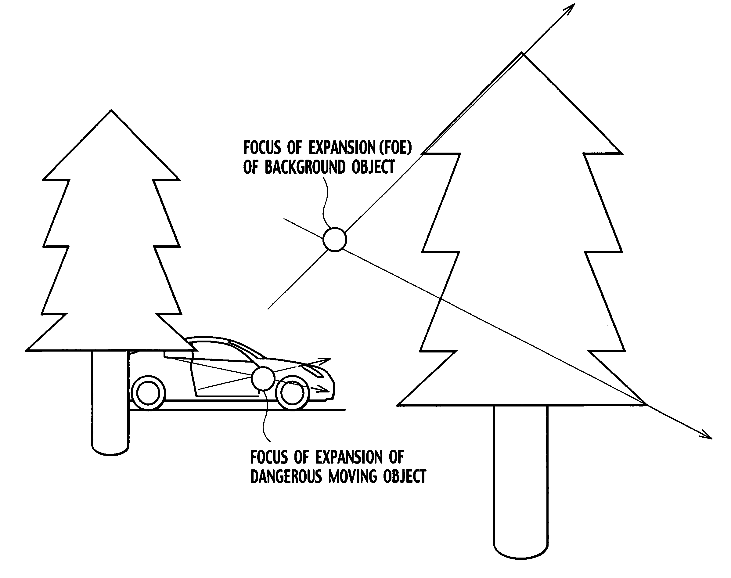
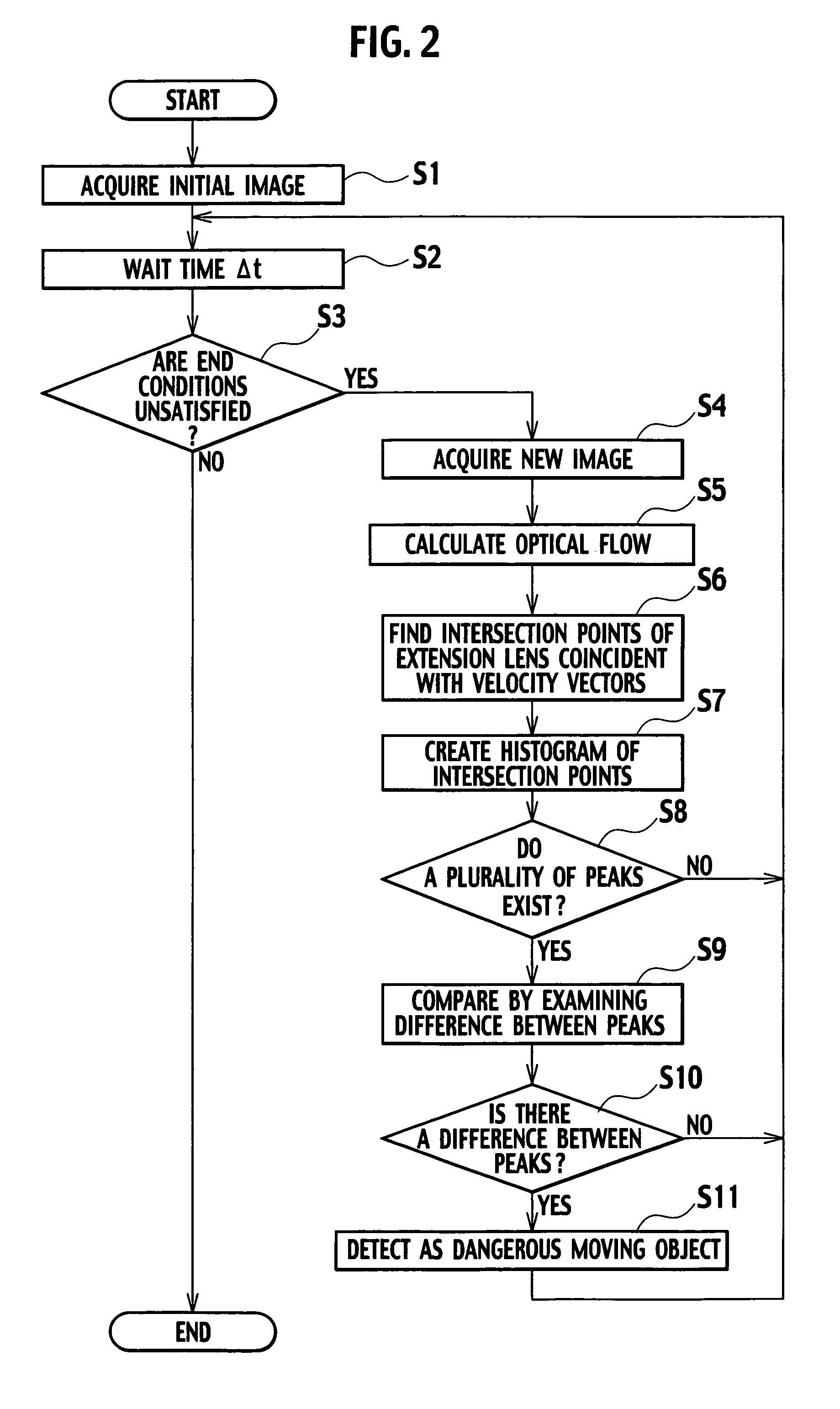
An aspect of the present invention provides a moving obstacle detecting device installed in or on a moving body for detecting moving obstacles in the vicinity of the moving body, the moving obstacle detecting device that includes an image capturing unit configured and arranged to capture an image of the surroundings of the moving body, an optical flow calculating unit configured to find an optical flow corresponding to characteristic points in the image captured with the camera, a focus of expansion calculating unit configured to calculate focus or foci of expansion of the motion vectors in the optical flow found by the optical flow calculating unit, a histogram creating unit configured to create a histogram of the distribution of the focus or foci of expansion calculated by the focus of expansion calculating unit, a peak test unit configured to detect at least one moving obstacle to test peaks in the histogram, the test determining whether or not the peaks correspond to the same object if two or more peaks exist in the histogram created by the histogram creating unit.

Description

BACKGROUND OF THE INVENTION[0001]The present invention relates to a moving obstacle detecting device installed on a vehicle or other moving body and serving to detect the existence of a moving obstacle in the vicinity of the moving body.[0002]An example of an existing device installed on a vehicle and serving to detect the existence of another vehicle or a pedestrian that will cross in front of the vehicle is disclosed in Japanese Laid-open Patent Publication No. Hei9-259282 (Patent Document 1). In Patent Document 1, an image captured by photographing the surroundings of the vehicle is divided into two regions, one in which a moving obstacle exists and one in which the obstacle does not exist, and the position and direction of movement of the obstacle is calculated based on output obtained from the two regions.[0003]The method of identifying the moving obstacle during this processing is to divide the image into small regions and calculate an overall estimated residual value for each...

Claims


Application Information

Patent Timeline
Patent Type & Authority Patents(United States)
IPC IPC(8): G06K9/00
CPCG06K9/00805G06T7/20G06V20/58
Inventor SANO, YASUHITO
Owner NISSAN MOTOR CO LTD
Learn More