
Light emitting diode lamp assembly

a technology of light-emitting diodes and lamps, which is applied in the direction of point-like light sources, semiconductor devices of light sources, lighting and heating apparatus, etc., can solve the problems of occupying a large space, generating more heat, and insufficient uniform illumination of led light, so as to reduce the electric power consumption of light-emitting assemblies, improve the efficiency of heat absorption and dissipation, and improve the safety of use

Inactive Publication Date: 2008-03-25
EDISON-OPTO
View PDF5 Cites 13 Cited by
  • Summary
  • Abstract
  • Description
  • Claims
  • Application Information

AI Technical Summary

Benefits of technology

"The present invention provides an LED lamp assembly that uses a plurality of linear-extended LED lighting sources for projecting lights, and a reflecting and heat-dissipating module for modulating projecting lights with larger lighting region and uniform illumination. The LED lamp assembly replaces the fluorescent lamp by the advantages mentioned above. The reflecting and heat-dissipating module can work with a thermal module for dissipating heat from the projecting lights, out of the LED lamp assembly. Each reflecting and heat-dissipating member is provided with a plurality of thermal fins for rising the efficiency of heat absorbing and dissipating. The technical effects of the present invention are that it solves the problem of illumination being not uniform enough and provides more commercial values to replace the fluorescent light."

Problems solved by technology

However, the light strength of the LED is controlled by stimulating voltage and has an obvious characteristic of emitting directionality, so the illumination of the light projected from the LED is not uniform enough to be applied as a lighting source of a wide-angle lighting apparatus.
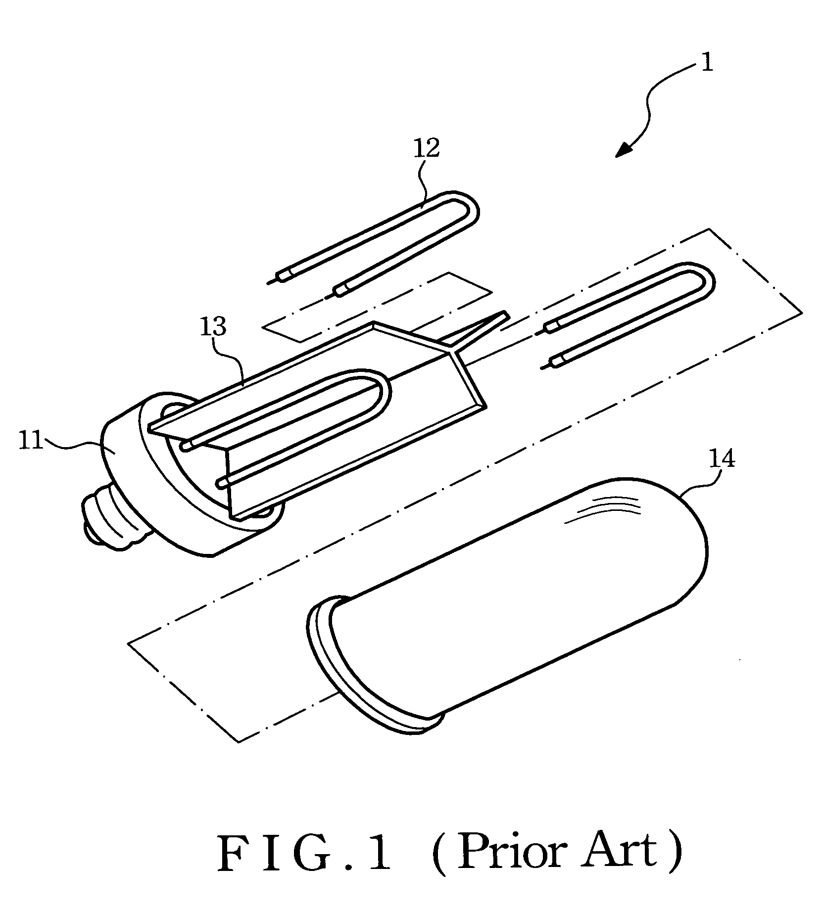
However, anybody may ask why the fluorescent lights 12 should be provided in the shape of “reversed U”, and it occupies a larger space and generates more heat.

Method used


Image

  • Light emitting diode lamp assembly
  • Light emitting diode lamp assembly
  • Light emitting diode lamp assembly

Examples


Embodiment Construction

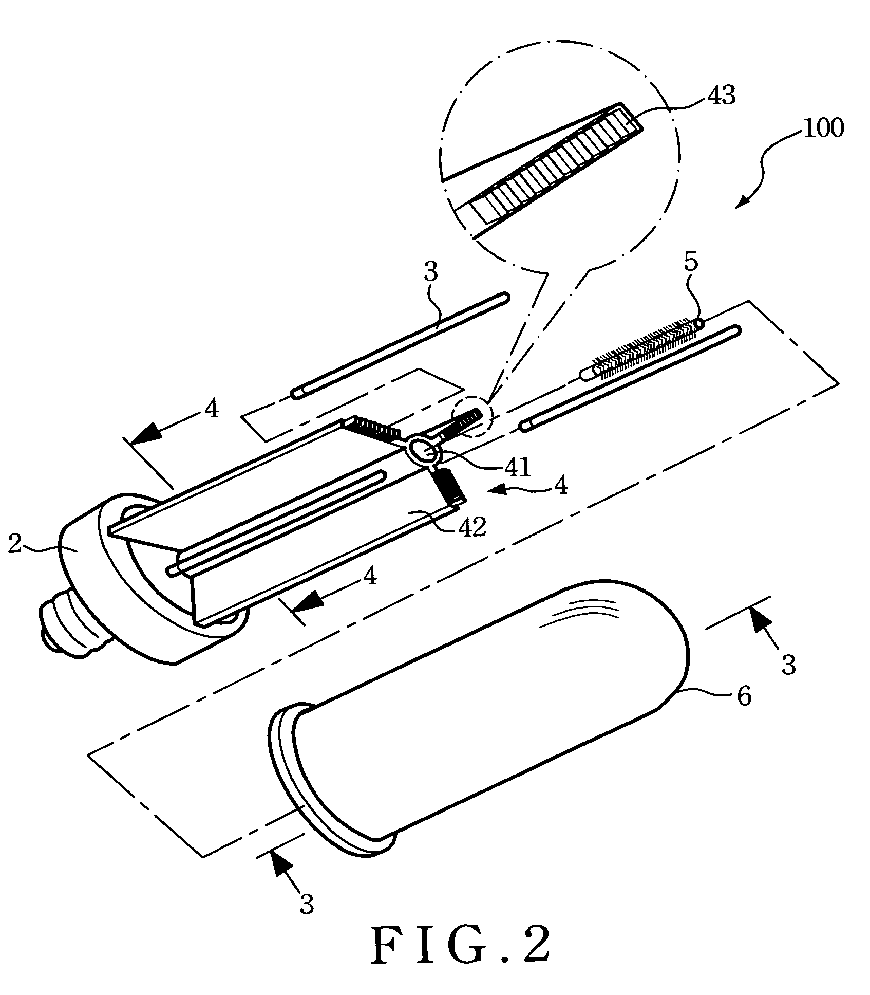
[0024]Since the linear-extended lighting emitting diode (LED) can be widely applied to many kinds of lamp assembly, the combined applications are too numerous to be enumerated and described, therefore a preferred embodiment of the present invention applied for a triple-shift LED lamp assembly herein is disclosed, and the LED lamp assembly, is replaced by a triple-shift LED lamp assembly described as follows.

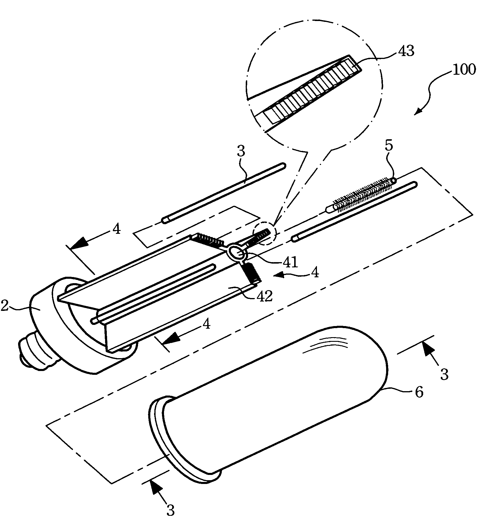
[0025]Please refer to FIG. 2 to FIG. 4, wherein FIG. 2 is a partially-exploded view illustrating a structure of a triple-shift LED assembly provided in accordance with a preferred embodiment of the present invention, FIG. 3 is a section view illustrating a 3-3 section view of FIG. 2, FIG. 4 is a top view illustrating the LED lamp assembly in accordance with the preferred embodiment of the present invention after a lampshade is removed. As shown in the figures, a triple-shift LED lamp assembly 100 includes a base 2, three linear-extended LED lighting sources 3, a reflecting and he...


PUM


Abstract

A Light Emitting Diode (LED) lamp assembly comprises a base, a plurality of linear-extended LED lighting sources, a reflecting and heat-dissipating module, and a thermal module. The linear-extended LED lighting sources are distributed and connected to the base for optionally projecting at least one projecting light and releasing light heat simultaneously. The reflecting and heat-dissipating module is provided with a central heat-dissipating region approximately located on a central region of all the LED lighting sources and a plurality of reflecting and heat-dissipating members radially extended from the central heat-dissipating region for separating the linear-extended LED light sources, reflecting the projecting light, absorbing and conducting the light heat. The thermal module is arranged within the central heat-dissipating region for dissipating the light heat absorbed and conducted by the reflecting and heat-dissipating members.

Description

FIELD OF THE INVENTION[0001]The present invention relates to a light emitting diode (LED) lamp assembly, and more particularly to a LED lamp assembly used a plurality of linear-extended LED lighting sources for projecting lights and a thermal module for heat dissipating.BACKGROUND OF THE INVENTION[0002]LED is an electronic element, which can radiate light when applying electric power. The lighting principle of LED is translating electric power to light energy, that is, doping a minute amount of carriers into a conjunction of P-type side and N-type side and continuously combining the minute amount of carriers with a major amount of carriers to form a LED. To be with the good performance of the LED radiation may need a large amount of pairs of electrons and holes, the space charge layers become narrower when applying a forward biased voltage, and then a major amount of carriers are doped into the P-type side and the N-type side according to Fermi characteristic energy level deviation....

Claims


Application Information

Patent Timeline
Patent Type & Authority Patents(United States)
IPC IPC(8): F21V29/00
CPCF21V29/773F21V29/505F21K9/135F21Y2101/02F21V3/00F21K9/232F21Y2115/10
Inventor SUN, TSUNG-TINGLIAO, HUNG-TAYEN, TZU-HSUANCHEN, PAO-SHEN
Owner EDISON-OPTO
Learn More