Push-on connector interface

a technology of push-on connectors and connectors, which is applied in the direction of coupling contact members, coupling device connections, coupling parts, etc., can solve the problems of requiring consuming time and forcing the user to use both hands and or a wrench

Inactive Publication Date: 2008-03-25
ANDREW LLC
View PDF26 Cites 83 Cited by
  • Summary
  • Abstract
  • Description
  • Claims
  • Application Information

AI Technical Summary

Benefits of technology

[0036]A third exemplary embodiment of the invention, as shown in FIGS. 11-15 with corresponding element notations as described above, applies a spring finger collar 33 as the first spring 19. The spring finger collar 33 is dimensioned to press fit upon the outer diameter of the connector end of the sleeve 11, creating a strong electro-mechanical interconnection and eliminating the need for machining operations related to forming the first groove 17. Alternatively, the spring finger collar 33 may be adapted to press fit against the inner diameter of the male connector body 5. In this configuration, the spring finger(s) 35 are formed to extend away from the male connector body 5, around the leading edge of the female connector body 1 to contact and bias against the inner diameter of the female connector body 1 bore 16.
[0037]As shown in FIGS. 13 and 14, the spring finger ring 33 has a plurality of outwardly projecting deflectable protrusions, here in the form of spring finger(s) 35 projecting from a cylindrical collar 37. A leading edge 39 of each spring finger 35 may be formed with an angled surface and or a smooth radius to reduce friction as the spring finger(s) 35 initially contact and deflect against the inner diameter of the bore 16 during female connector body 1 to male connector body 5 mating. The deflection of each spring finger 35 creates a strong bias against the inner diameter of the bore 16, resulting in a secure electrical interconnection between the female connector body 1 and male connector body 5 as shown in FIG. 15.
[0039]The invention provides a simplified and cost effective connector interface for use with existing standard threaded connectors. The invention allows a user to quickly connect and disconnect interconnections without time consuming threading and or additional tools. Further, the invention provides multiple bias points and connection surfaces that create a secure mechanical and high quality electrical interconnection. Additional electrical shielding is also provided by the first spring multiple bias points and connection surfaces, further isolating the interconnection from high frequency signal leakage and or interference.

Problems solved by technology

The high frequency electrical characteristics of the interconnection formed with the outer conductor may be less than satisfactory because of the absence of an electrical connection at areas between each of the spring fingers.
However, the comparatively complex BNC connector is significantly more expensive to manufacture than Type F. Both BNC and Type F connectors are typically used in low signal level and or inexpensive consumer applications.
The threaded outer collar requires multiple turns to fully seat the interconnection, consuming time and forcing the user to use both hands and or a wrench.
Where connections are frequently changed, such as at a patch panel or with testing equipment, screwing and unscrewing the threaded outer collar becomes a burden.

Method used


Image

  • Push-on connector interface
  • Push-on connector interface
  • Push-on connector interface

Examples


Embodiment Construction

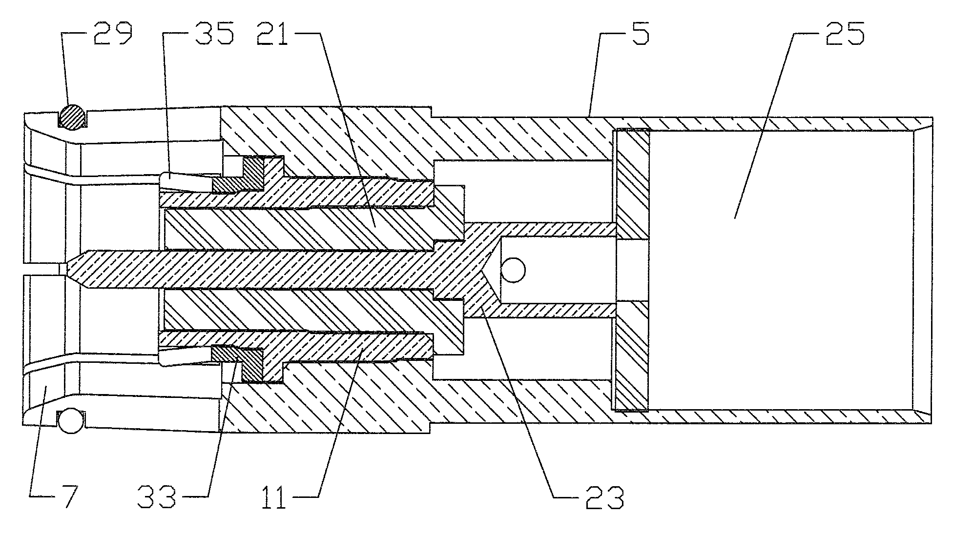
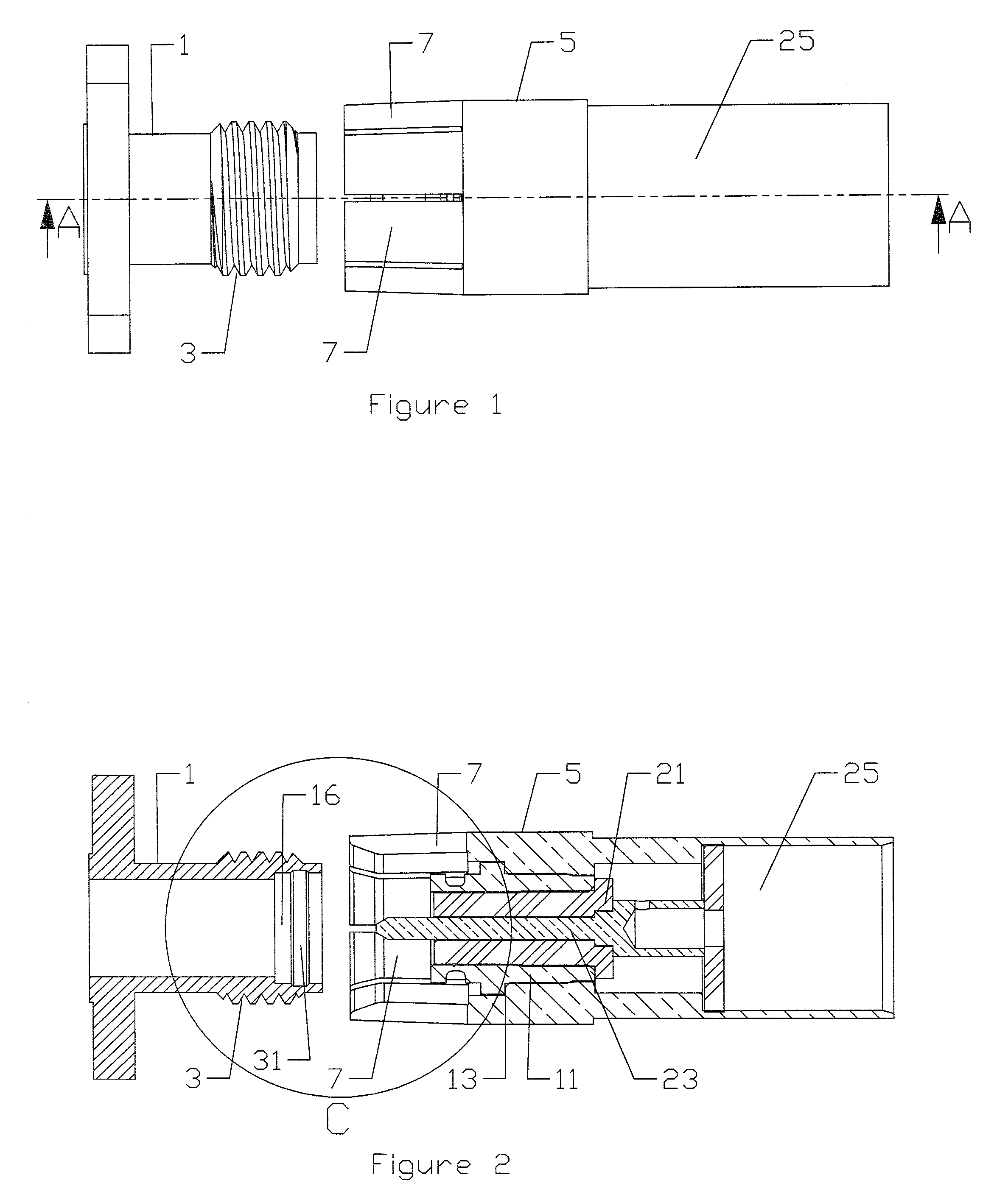
[0027]The invention is described with respect to FIGS. 1-10 in a standard SMA female connector configuration. One skilled in the art will appreciate that the invention is similarly applicable to Type N connectors and or other standard or proprietary connector configurations having an end bore which allows an outer diameter surface of the female portion to be contacted also upon an inner diameter surface.

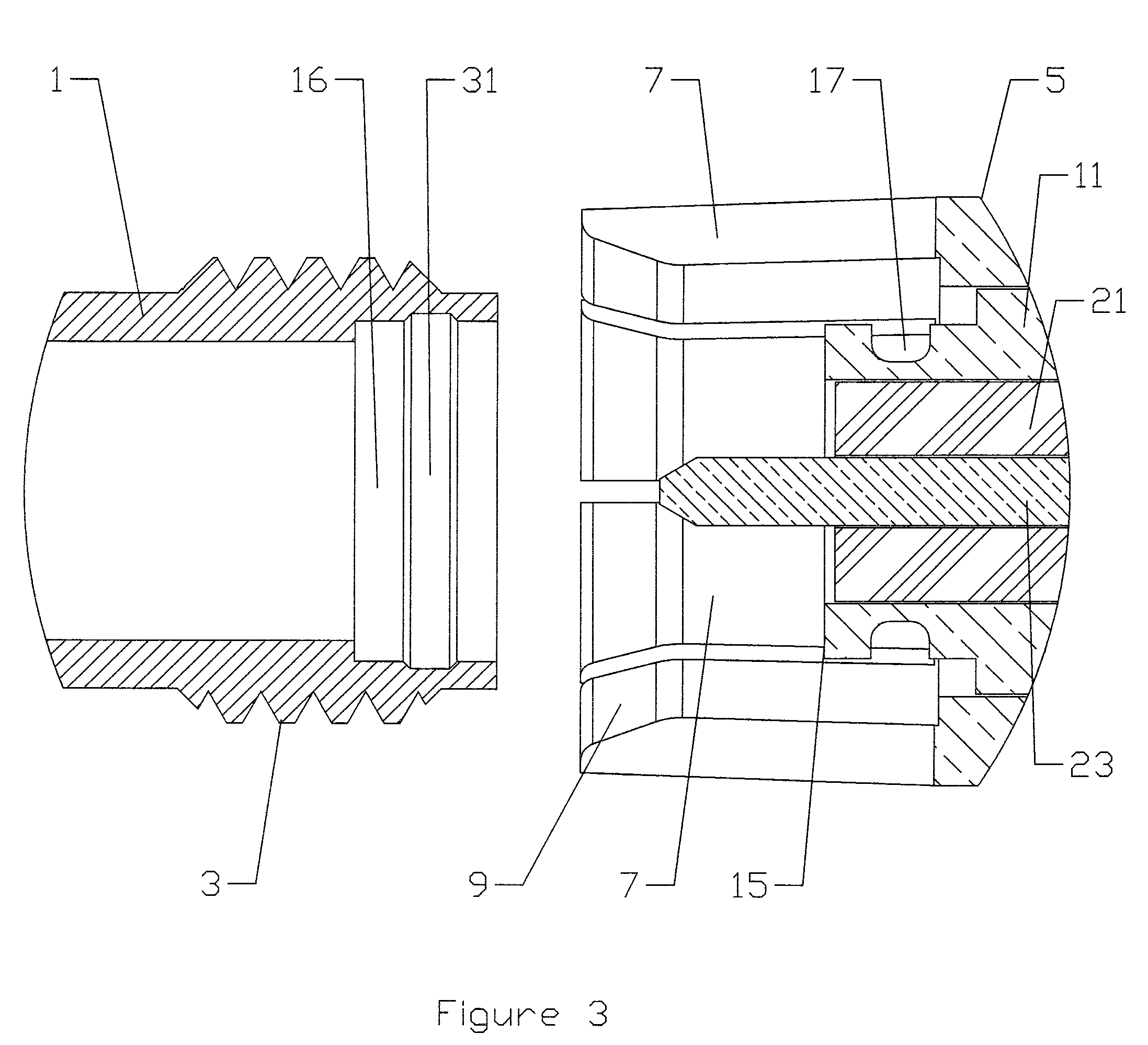
[0028]As shown in FIGS. 1-5, a standard SMA female connector body 1, shown here adapted for panel face mounting, has threads 3 on an outer diameter surface. Normally, the threads 3 are engaged by a rotatable outer threaded collar of an SMA male connector body. A male connector body 5, according to a first exemplary embodiment of the invention, contacts the threads 3 with a plurality of outer spring finger(s) 7 spaced around a front end of the male connector body 5.

[0029]The outer spring finger(s) 7 are adapted to form an interference fit over and against the threads 3 when the male c...


PUM


Abstract

A push-on connector interface and associated spring ring adapted for use with, for example, existing standardized threaded female connectors, for example SMA or Type N connectors. A plurality of spring fingers of the male connector body engage the, typically threaded, outer diameter surface of the female connector body. A sleeve within the male connector body may be adapted to extend within a bore of the female connector body. A spring or spring ring located, for example, positioned within a groove or press-fit upon the sleeve has a plurality of deflectable protrusions which deform between the sleeve and an inner diameter surface of the bore and or are biased against the inner diameter surface. The connections formed by the bias of spring fingers and the deformation and or bias of the spring or spring ring creating a reliable mechanical and electrical interconnection between the male and female connector bodies.

Description

CROSS REFERENCE TO RELATED APPLICATIONS[0001]This is a continuation-in-part of application Ser. No. 10 / 707,912, filed Jan. 23, 2004.BACKGROUND OF INVENTION[0002]1. Field of the Invention[0003]The invention relates to a push-on electrical connector interface. More particularly the invention relates to a push-on coaxial connector interface for use with both modified and standard connector interfaces adapted for interconnection via a threaded coupling nut.[0004]2. Description of Related Art[0005]Electrical connectors used in RF applications have become standardized to allow interoperability of equipment from different manufacturers. Examples of standard connector types include: SMA, Type N, BNC and Type F (CATV) connectors. Male Type F connectors include a threaded collar which mates to threads on the female interface to retain the interconnection. Alternatively, Male Type F connectors are available with spring fingers which form an interference fit when pushed over the threaded portio...

Claims


Application Information

Patent Timeline
Patent Type & Authority Patents(United States)
IPC IPC(8): H01R9/05H01R13/24H01R13/627H01R13/62H01R13/646
CPCH01R13/6277H01R24/40H01R2103/00H01R13/62
Inventor WLOS, JAMESPAYNTER, JEFFREY
Owner ANDREW LLC
Why Eureka
Try Eureka