System and method for employing variable magnetic flux bias in an amplifier

a variable magnetic flux and amplifier technology, applied in the field of amplifiers, can solve the problems of undesirable saturation of the output transformer, lack of fidelity of the amplifier design, and loss of power at the lower frequency end of the audio spectrum, and achieve the effect of minimizing magnetic saturation within the output transformer

Inactive Publication Date: 2008-03-25
GIOVANNOTTO ROBERTO MICHELE
View PDF7 Cites 12 Cited by
  • Summary
  • Abstract
  • Description
  • Claims
  • Application Information

AI Technical Summary

Benefits of technology

[0013]The control circuitry may be adjusted such that a quiescent magnetic bias level is maintained within the output transformer. In this embodiment, the selected quiescent magnetic bias level produces desired audio effects as, for example, harmonically pleasing sounds. In this embodiment, the amplifier system may be employed as a musical instrument amplifier, such as a guitar amplifier. In another embodiment, the control circuitry may be adjusted so that a magnetic saturation within the output transformer is minimized, and the amplifier system may be employed as a high-fidelity amplifier system.

Problems solved by technology

Thus, amplifier designs using an output transformer may suffer from a lack of fidelity and loss of power at the lower-frequency end of the audio spectrum.
If the quiescent magnetic bias level is not close to a zero level, the alternating magnetic flux swing within the output transformer's core may cause magnetic saturation.
Saturation of the output transformer is undesirable because a greater magnetic flux swing is needed within the output transformer to maintain output power and minimize total harmonic distortion at lower signal frequencies.
However, this technique reduces the relative magnetic permeability of the transformer's core and adversely affects inductance and the low-frequency response of the output transformer.
However, the shunt feed technique suffers from the requirement for a physically large and expensive DC blocking capacitor.
The use of smaller shunt feed capacitors adversely effects low-frequency amplifier response to such a degree that shunt feed amplifier systems in the audio market perform only marginally better than amplifier systems employing a physical gap.
However, this technique using a current sensing resistor suffers from several problems, including increased distortion due to the placement of the current sensing resistor in the plate or cathode circuit of the amplifier.
In practical applications, asymmetries in output transformer windings due to manufacturing tolerances may result in only partial cancellation of the DC and low-frequency magnetomotive force produced by the first primary winding.
Finally, this technique does not correct for remnant induction in the output transformer.

Method used


Image

  • System and method for employing variable magnetic flux bias in an amplifier
  • System and method for employing variable magnetic flux bias in an amplifier
  • System and method for employing variable magnetic flux bias in an amplifier

Examples


Embodiment Construction

[0025]The embodiments discussed herein are illustrative examples of the present invention. As these embodiments of the present invention are described with reference to illustrations, various modifications or adaptations of the methods and / or specific structures described may become apparent to those skilled in the art. All such modifications, adaptations, or variations that rely upon the teachings of the present invention, and through which these teachings have advanced the art, are considered to be within the scope of the present invention. Hence, these descriptions and drawings should not be considered in a limiting sense, as it is understood that the present invention is in no way limited to only the embodiments illustrated.

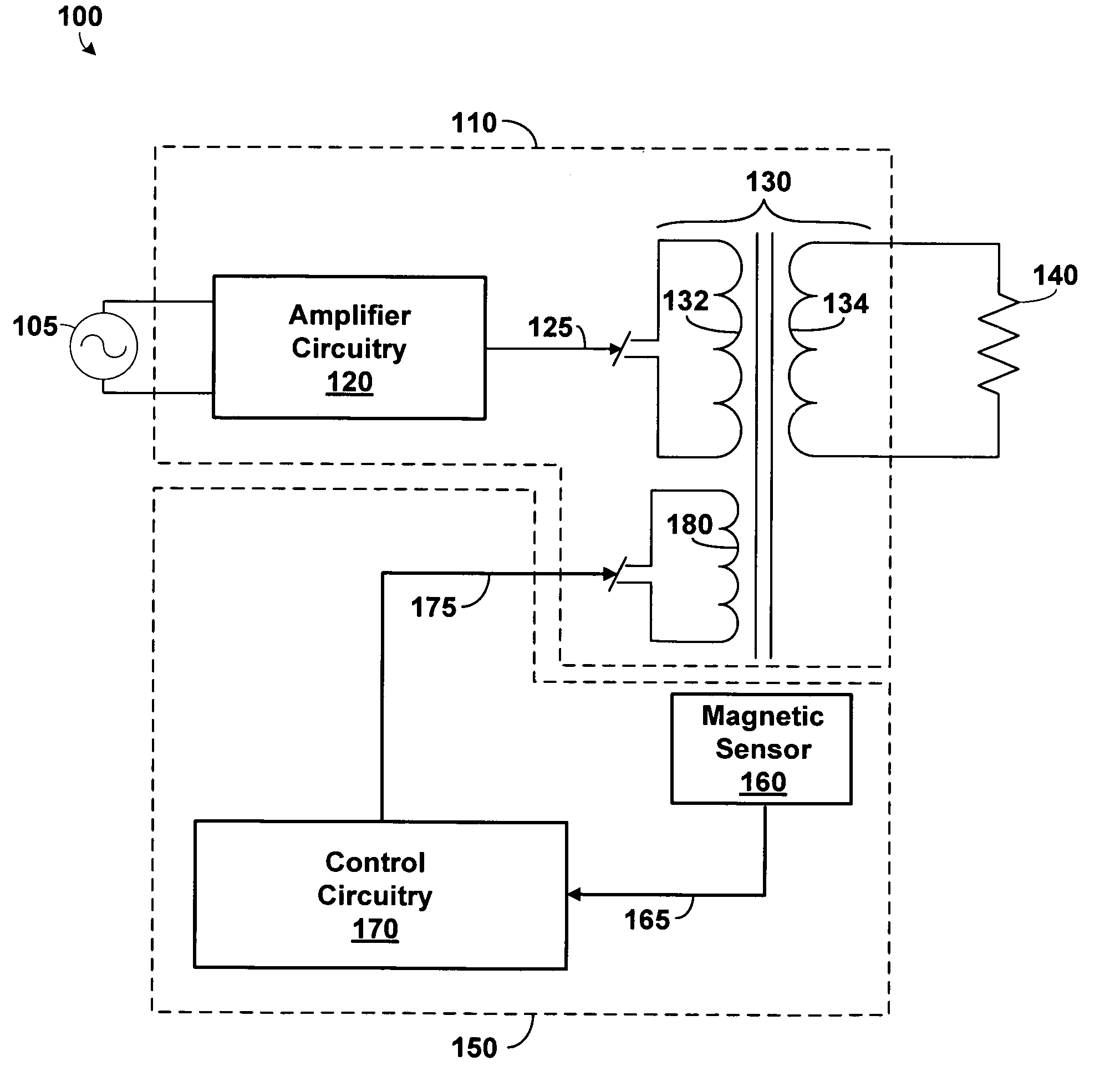
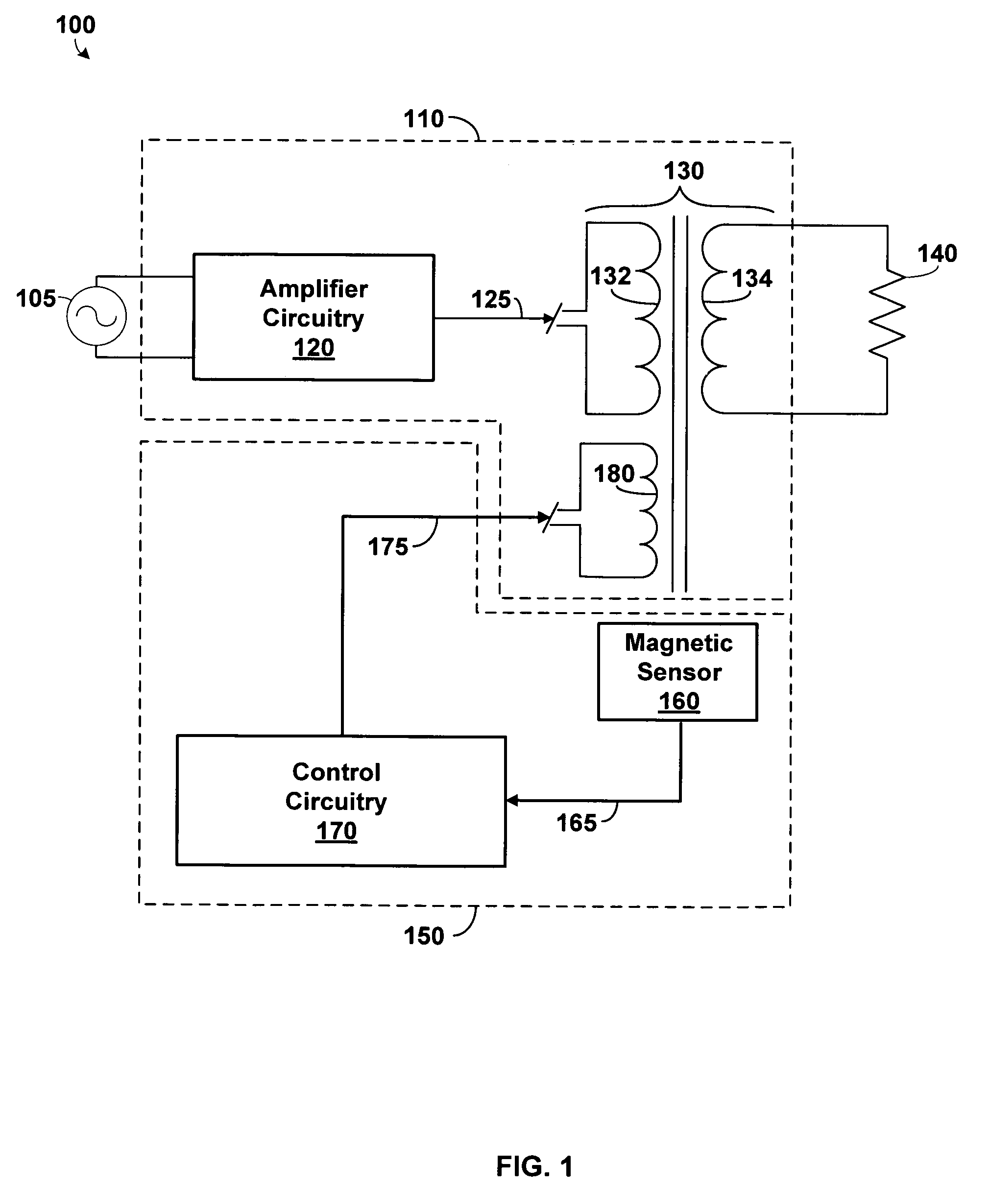
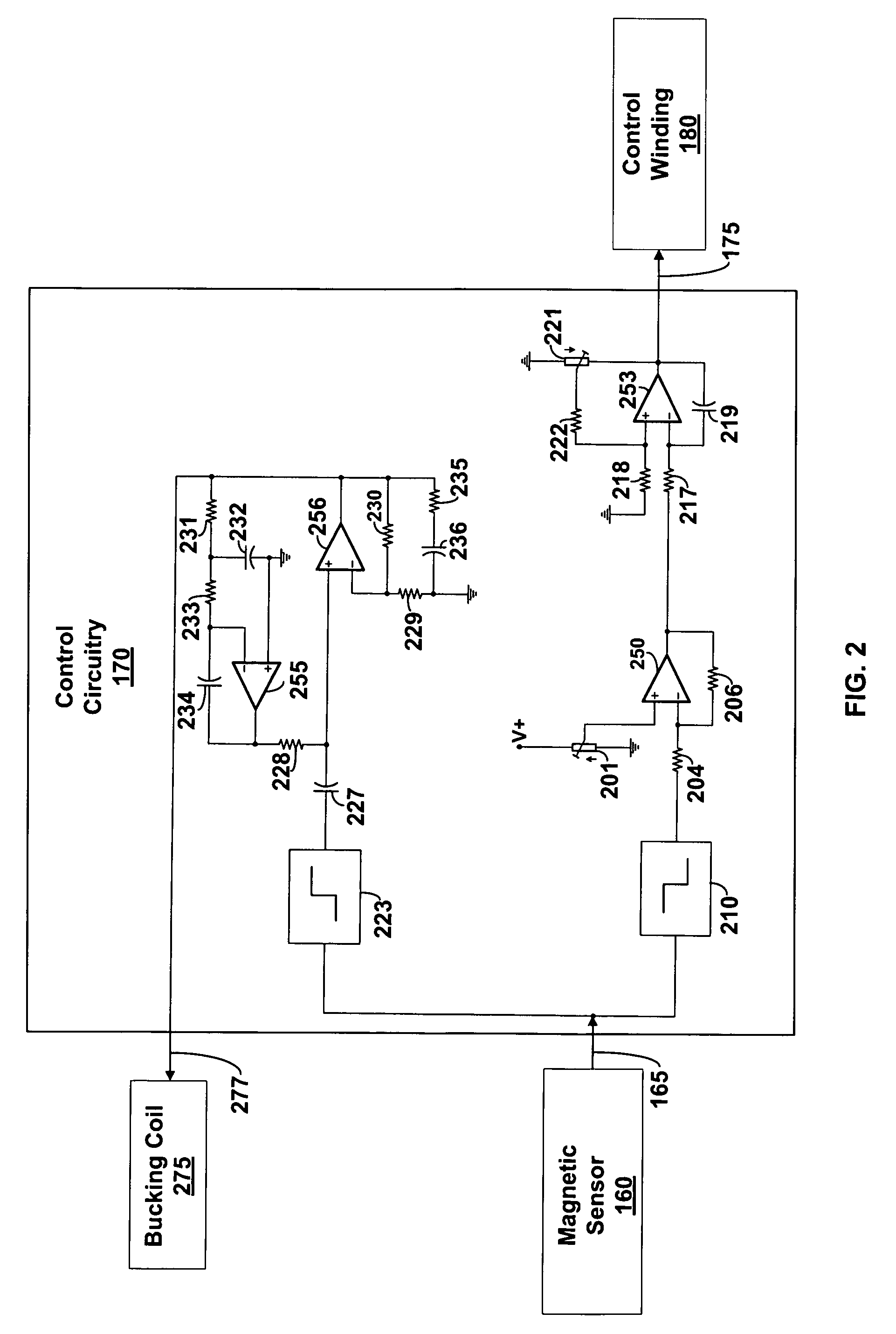
[0026]A magnetic sensor is placed in proximity to an output transformer of an amplifier to sense the leakage magnetic flux emanating from the output transformer. The leakage magnetic flux is proportional to the total magnetic flux within the output transforme...


PUM


Abstract

A system and method for employing variable magnetic flux bias in an amplifier. The amplifier system comprises an output transformer and a magnetic sensor configured to sense a first magnetic flux of the output transformer. The magnetic sensor generates a flux signal responsive to the first magnetic flux. Control circuitry is configured to receive the flux signal and to generate a control signal responsive to the flux signal. A winding is configured to receive the control signal and to induce a second magnetic flux within the output transformer responsive to the control signal, the second magnetic flux having opposite polarity to the first magnetic flux. The second magnetic flux may maintain a non-zero quiescent magnetic bias level within the output transformer, or may substantially cancel or null the DC and low-frequency subsonic components of the first magnetic flux.

Description

CROSS-REFERENCE TO RELATED APPLICATIONS[0001]This application claims the benefit of U.S. Provisional Application Ser. No. 60 / 683,549 titled “Audio Frequency Amplifier Employing Variable Magnetic Flux Bias,” filed May 19, 2005, which is hereby incorporated by reference.BACKGROUND OF THE INVENTION[0002]1. Field of the Invention[0003]The present invention relates generally to amplifiers, and more particularly to a system and method of employing variable magnetic flux bias in an amplifier.[0004]2. Description of the Related Art[0005]The output power and distortion of an audio frequency amplifier using an output transformer is partially dependent on the specific magnetic properties of the output transformer. Output transformers are commonly used with vacuum tube amplifiers. Such output transformers are used to match the higher impedance of the vacuum tubes to the typically lower impedance of the loudspeakers. Output transformers may also be used for isolation of the amplifier from the lo...

Claims


Application Information

Patent Timeline
Patent Type & Authority Patents(United States)
IPC IPC(8): H03F1/00
CPCH03F1/565H03F3/181H03F2200/03H03F2200/541
Inventor GIOVANNOTTO, ROBERTO MICHELE
Owner GIOVANNOTTO ROBERTO MICHELE
Why Eureka
Try Eureka