Reverse optical mastering for data storage disks

a data storage disk and reverse optical technology, applied in applications, instruments, other domestic articles, etc., can solve the problems of increasing data readback noise, track pitch approaching finite size, and designer not being able to independently specify the desired parameters for replica land, etc., to achieve high information capacity

Inactive Publication Date: 2008-03-25
MAX BLU TECH
View PDF51 Cites 10 Cited by
  • Summary
  • Abstract
  • Description
  • Claims
  • Application Information

AI Technical Summary

Benefits of technology

[0024]The present invention may further provide the step of controlling the thickness of the layer of the photosensitive material to correspond to a desired depth of the replica grooves. The specified and controlled thickness of the photosensitive material depends on master recording system spot size, desired track pitch, and desired depth of replica grooves.

Problems solved by technology

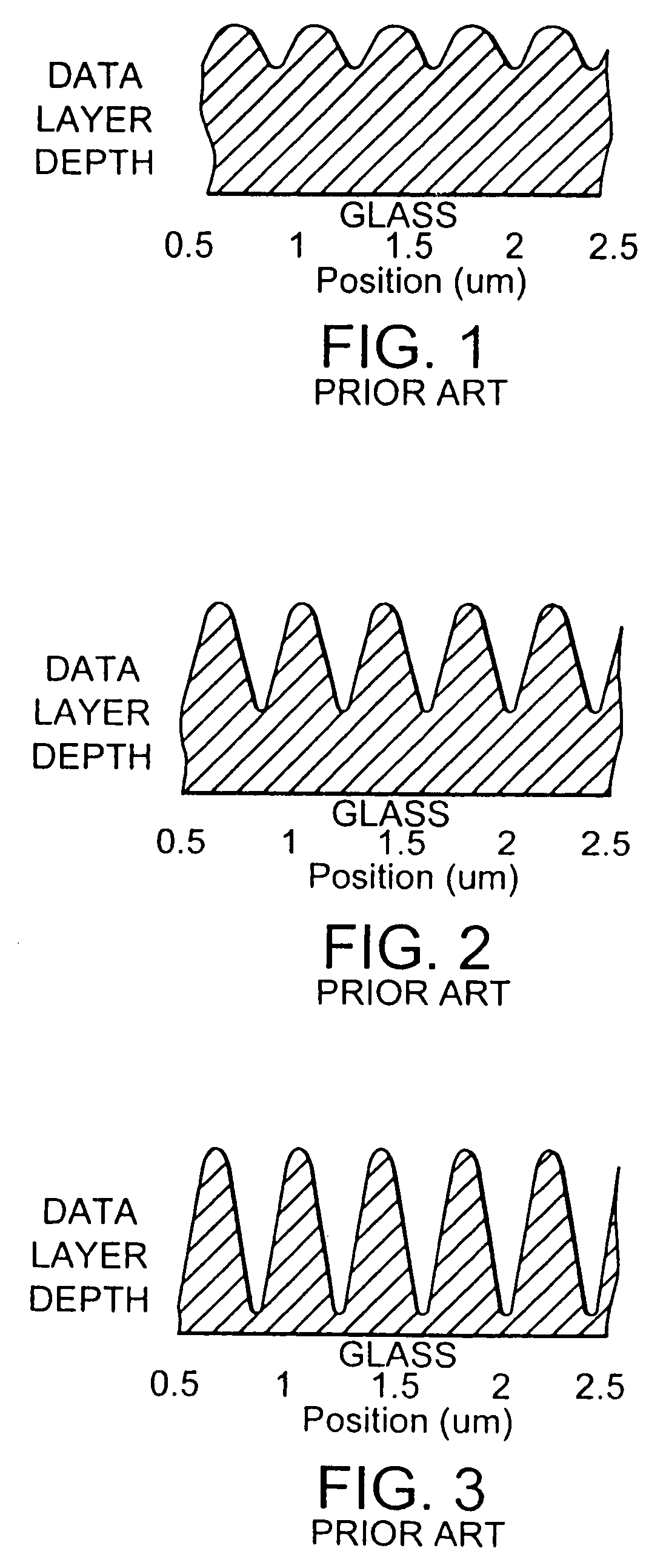
Roughness of lands worsens with deepening of grooves, resulting in additional noise in data readback.
More problems occur when the track pitch approaches the finite size of the mastering spot size.
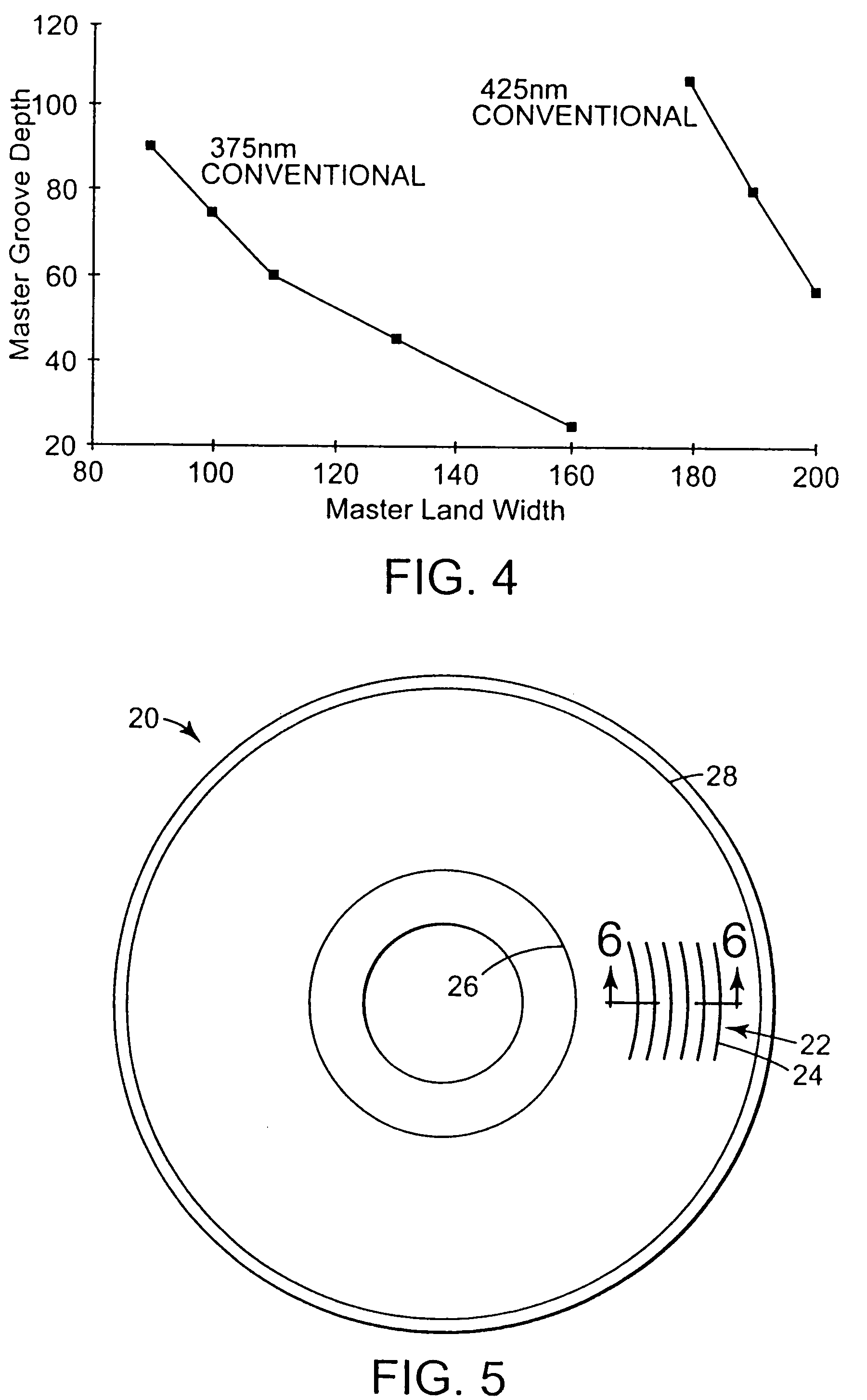
This means the designer may not independently specify the desired parameters for replica land width and replica groove depth.
A secondary problem for conventional mastering is that the land width precision is limited by mechanical track pitch precision (e.g., mechanical precision of master recording system), which is increasingly difficult to control as track pitch decreases.

Method used


Image

  • Reverse optical mastering for data storage disks
  • Reverse optical mastering for data storage disks
  • Reverse optical mastering for data storage disks

Examples


Embodiment Construction

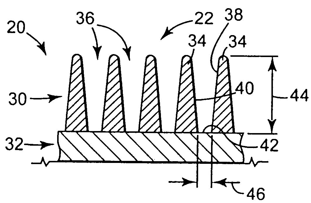
[0050]The present invention includes a data storage master disk and optical disk mastering process for making the unique data storage master disk. The process in accordance with the present invention provides for a master data storage disk having grooves which extend down to the master substrate, resulting in deep, flat, and wide master disk grooves. The master disk can be used in a disk molding process which includes a reverse mastering / inverse stamping process, resulting in replica disks having wide, flat lands with sharp edges, and deep grooves relative to replica disks formed using conventional mastering processes. As such, the present invention is particularly useful in enabling flexible design of surface relief geometry for molded data storage disks containing a high density of information. This includes the ability to create wide, flat land features even in replica disks having a track pitch of less than two times the mastering system laser beam spot size.

[0051]In FIG. 5, a d...


PUM

PropertyMeasurementUnit
widthaaaaaaaaaa
groove depthaaaaaaaaaa

Abstract

A data storage master disk and method of making a data storage master disk. The data storage disk master is for use in a data storage disk replication process. The data storage disk molding processes produces replica disks having a surface relief pattern with replica lands and replica grooves. The method includes providing a master substrate. The master substrate is at least partially covered with a layer of photosensitive material. A surface relief pattern having master lands and master grooves is recorded in the data storage disk master, including the steps of exposing and developing the photosensitive material. The exposing and developing of a specified thickness of photosensitive material is controlled to form master grooves extending down to a substrate interface between the master substrate and the layer of photosensitive material, such that the width of the master grooves at the substrate interface corresponds to a desired width of the replica lands.

Description

[0001]This application is a continuation of U.S. application Ser. No. 09 / 850,252, filed May 7, 2001 now U.S. Pat. No. 6,728,196, which is a divisional application of U.S. application Ser. No. 09 / 730,246, filed Dec. 5, 2000 now U.S. Pat. No. 6,890,704, which is a continuation-in-part (CIP) of U.S. application Ser. No. 09 / 055,825, filed Apr. 6, 1998, now abandoned. The entire content of each of the aforementioned applications is incorporated herein by reference.TECHNICAL FIELD[0002]The present invention relates generally to the field of manufacture of optical data storage disks, and in particular, to an optical disk mastering process for use in a disk molding process, capable of molding data storage disks containing a high density of information.BACKGROUND OF THE INVENTION[0003]Optical disks are produced by making a master which has a desired surface relief pattern formed therein The surface relief pattern is created using an exposure step (e.g., by laser recording) and a subsequent d...

Claims


Application Information

Patent Timeline
Patent Type & Authority Patents(United States)
IPC IPC(8): G11B7/24G11B7/007G11B7/26G11B23/00
CPCG11B7/261G11B23/0085G11B7/24G11B7/24091G11B7/263Y10S425/81
Inventor EDWARDS, JATHAN D.
Owner MAX BLU TECH
Why Eureka
Try Eureka