Economically expansible switching network

a switching network and economic expansion technology, applied in data switching networks, frequency-division multiplexes, instruments, etc., can solve the problems of fast exceeding the capacity of copper networks and electro-mechanical switching systems, and limited deployment to high-revenue-generating applications

Active Publication Date: 2008-03-25
BAY MICROSYSTEMS INC
View PDF4 Cites 12 Cited by
  • Summary
  • Abstract
  • Description
  • Claims
  • Application Information

AI Technical Summary

Problems solved by technology

In recent years, however, there has been an explosive growth in demand for telecommunications services that employ a wide variety of new end-user equipment This demand quickly exceeded the capacity of the copper networks and electro-mechanical switching systems.
In the early stages of optical fiber networks, however, deployment was limited to high-revenue-generating applications.
This limited deployment was due to communications-equipment manufacturers making network components using unique, proprietary architectures.
The result of which, of course, was that the network components from one manufacturer did not work with other manufacturers' network components.

Method used


Image

  • Economically expansible switching network
  • Economically expansible switching network
  • Economically expansible switching network

Examples


Embodiment Construction

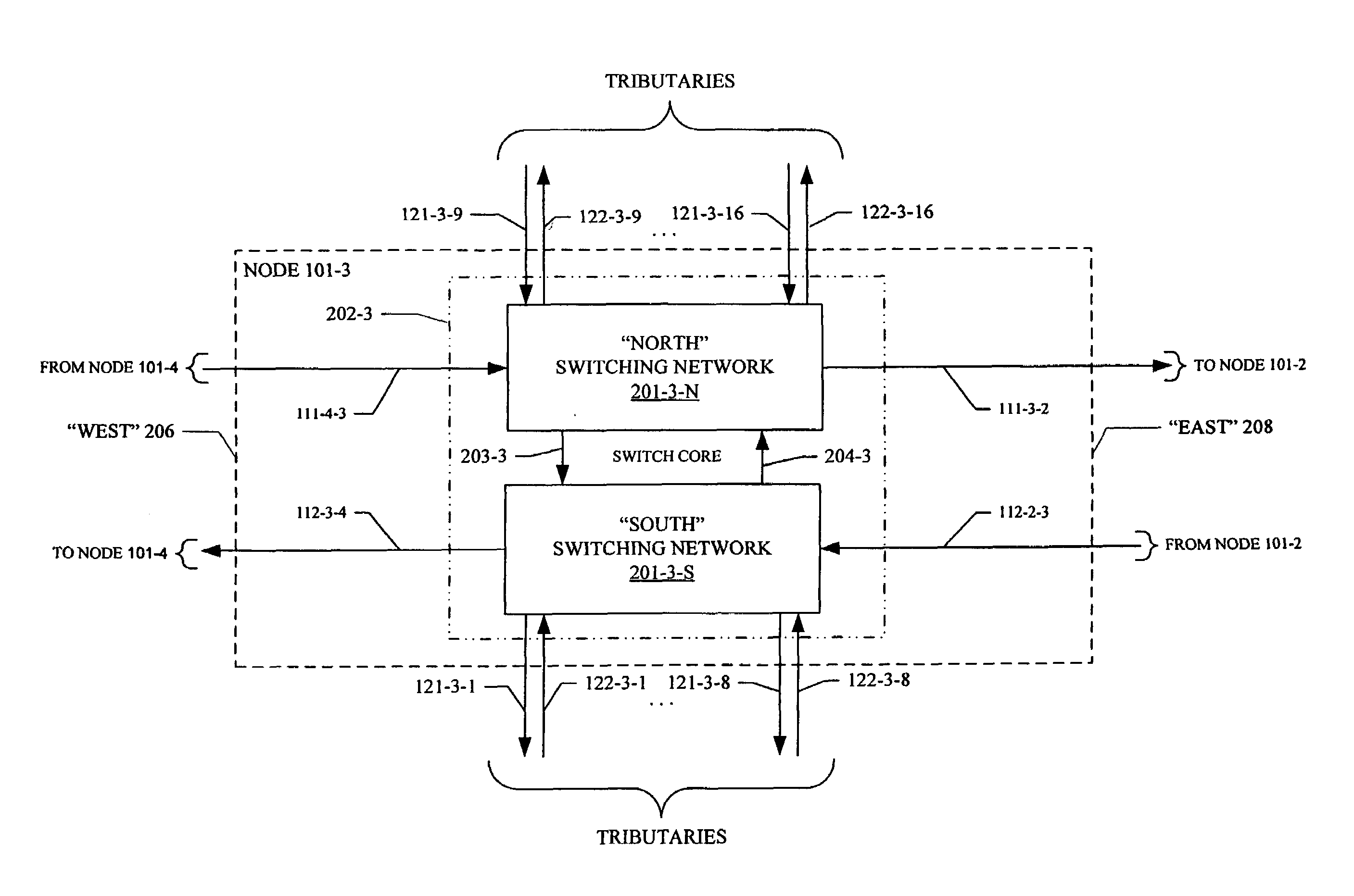
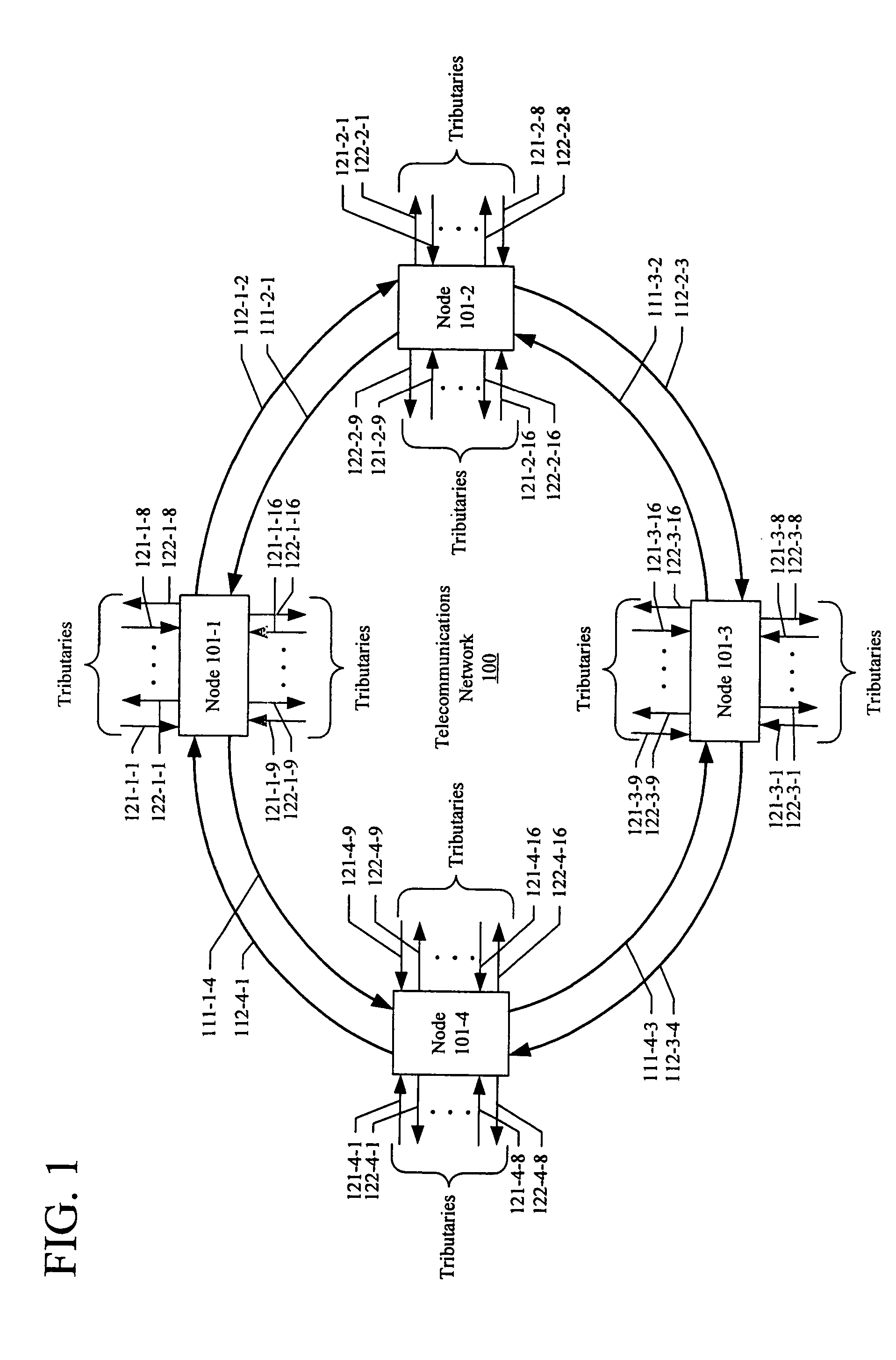
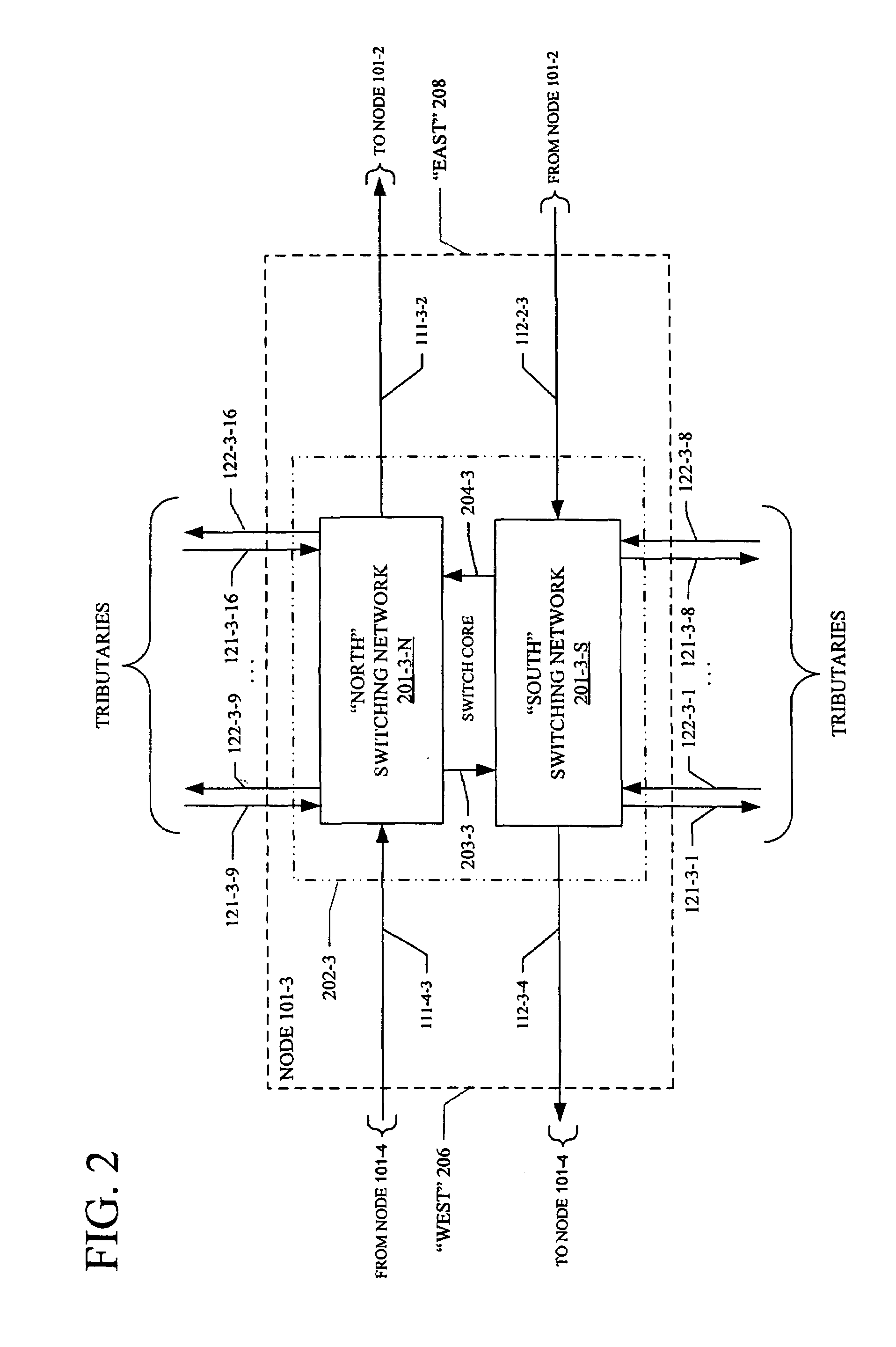
[0028]FIG. 1 depicts a block diagram of an illustrative embodiment of the present invention, in the context of telecommunications network 100, which is a SONET / SDH ring network operating as a bidirectional line switched ring (“BLSR”). Telecommunications network 100 comprises four nodes, nodes 101-1 through 101-4, in accordance with the illustrative embodiment of this invention, which are interconnected by two sets of optical fibers, each of which carries an OC-768. Therefore, each node comprises two OC-768 line inputs and two OC-768 line outputs.

[0029]Although the illustrative embodiment uses SONET / SDH protocol, it will be clear to those skilled in the art how to make and use embodiments of the present invention that use other protocols. Although the illustrative embodiment is a ring network, it will be clear to those skilled in the art how to make and use embodiments of the present invention in which some or all of the nodes are interconnected in a mesh topology or non-ring network...


PUM


Abstract

A telecommunications switching node comprising a plurality of input and output (I / O) ports configured to receive and transmit telecommunications signals, a switching core comprising a plurality of switching networks and a backplane connecting each of the plurality of I / O ports to each of the switching networks in the switching core. A non-blocking path is provided for each communications signal from any of the input ports to any of the output ports via one of the switching networks in the switching core. Further, the switching system effects a non-blocking path via all of the switching networks in the switching core. Advantageously, the switching core comprises a pair of switching networks. Further, this telecommunications switching node is expandable by adding a second switching core comprising a pair of switching networks to the node. One or more of the plurality of I / O ports may include a switching network to effect connection through the backplane to both pairs of switching networks.

Description

FIELD OF THE INVENTION [0001]The present invention relates to the field of telecommunications, and, more specifically, to an upgradeable architecture for a composite add / drop multiplexor, which is commonly used in high-speed backbone networks (e.g., SONET / SDH networks, etc.).BACKGROUND OF THE INVENTION [0002]In the not-too-distant past, there were relatively few telecommunications networks. These telecommunications networks supported a limited assortment of end-user equipment with electro-mechanical switching systems interconnected with copper wire. In recent years, however, there has been an explosive growth in demand for telecommunications services that employ a wide variety of new end-user equipment This demand quickly exceeded the capacity of the copper networks and electro-mechanical switching systems. To meet this demand, service providers old and new turned to optical fiber systems interconnected by computer-controlled (electronic) switching systems.[0003]Today, high-capacity...

Claims


Application Information

Patent Timeline
Patent Type & Authority Patents(United States)
IPC IPC(8): H04L12/28H04L1/22H04Q11/04
CPCH04L1/22H04J3/085H04J2203/0012H04J2203/0026H04J2203/0042H04J2203/006
Inventor PITIO, WALTER MICHAEL
Owner BAY MICROSYSTEMS INC
Why Eureka
Try Eureka