
Method of monitoring and controlling a laser diode

a laser diode and monitoring and control technology, applied in the direction of semiconductor lasers, distance measurement, instruments, etc., can solve the problems of insufficient control bits used to set the bias current in a particular application, inability to reliably receive too dim light, and inability to overcome changes in light power. , to achieve the effect of slope efficiency

Inactive Publication Date: 2008-03-25
AVAGO TECHNOLOGIED FIBER IP SINGAPORE PTE LTD
View PDF9 Cites 26 Cited by
  • Summary
  • Abstract
  • Description
  • Claims
  • Application Information

AI Technical Summary

Benefits of technology

"The patent describes a method for controlling a laser diode by measuring the average light output power and comparing it to a desired target range. If the average power is not within the range, the method measures the slope efficiency of the laser diode by measuring two light output powers at different bias conditions. Based on the measured slope efficiency, a new bias current is calculated to produce a new average light output power within the target range. The technical effect of this method is to provide a more accurate and efficient way to control the output of laser diodes."

Problems solved by technology

Pulses that are too dim might not be reliably received by a photodetector at the opposite end of the optical fiber link, and pulses that are too bright might create an eye-hazard for a human operator.
The control bits used to set the bias current in a particular application might not be sufficient to overcome changes in light power arising from aging or temperature effects.
However, this approach can take a long time, especially if the light power drifts outside the target range.
Even if the light power is within the target range, determining the exact value of the threshold current is quite difficult and can take several measurements.

Method used


Image

  • Method of monitoring and controlling a laser diode
  • Method of monitoring and controlling a laser diode
  • Method of monitoring and controlling a laser diode

Examples


Embodiment Construction

I. Exemplary Diode Characteristic

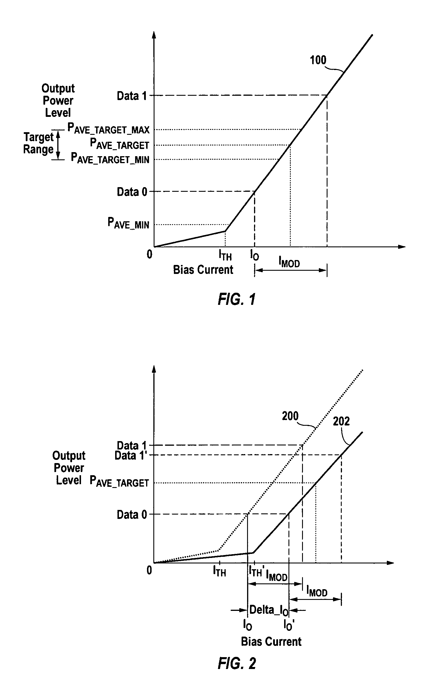
[0021]FIG. 1 shows a plot 100 of average light output power (“PAVE”) versus bias current for an exemplary laser diode. PAVE is the average output power (typically expressed in mW) when the laser diode is transmitting a 1-0-1-0-1 . . . data stream. A DATA 0 (LOW) condition is when the laser diode is biased at a low bias current I0, and a DATA 1 (HIGH) condition is when the laser is biased at a high bias current I0+IMOD. PAVE is the average of the output power level at DATA 1 and the output power level at DATA 0. For a fixed IMOD, PAVE increases slightly with increasing bias current until the threshold current (“ITH”) 101 is reached, after which PAVE more rapidly increases with increasing bias current. The relationship between PAVE and bias current above PAVE—MIN is called the slope efficiency (“SE”).

[0022]Photodiodes are typically used as the light detectors in optical feedback loops. Such photodiodes have leakage (“dark”) current. Measuring the SE ab...


PUM


Abstract

A method of controlling a laser diode measures an average light output power of the laser diode and compares the average light output power to a desired average light output power within a target range. If the average light output power is not within the target range, the slope efficiency is determined by measuring two light output powers at two different bias conditions. Each of the two light output powers is greater than a selected minimum light output power, which insures that each measurement occurs within the slope efficiency portion of the laser diode curve. A new bias current for the laser diode is calculated based on the measured slope efficiency so as to produce a new average light output power within the target range.

Description

CROSS-REFERENCE TO RELATED APPLICATIONS[0001]Not applicable.STATEMENT REGARDING FEDERALLY SPONSORED RESEARCH OR DEVELOPMENT[0002]Not applicable.REFERENCE TO MICROFICHE APPENDIX[0003]Not applicable.BACKGROUND OF THE INVENTION[0004]Optical fiber communication systems (“OFCS”) use modulated light to transmit information over optical fibers. Unlike electronic transmissions, optical transmissions are not susceptible to electromagnetic noise and interference, and provide very broad bandwidth. Light emitting devices, such as laser diodes, are used to produce light pulses that are transmitted on the OFCS. Examples of suitable laser diodes include distributed feedback (“DFB”) lasers, Fabry-Perot (“FP”) lasers, and vertical-cavity surface-emitting lasers (“VCSELs”).[0005]It is generally desirable that a light emitting device used in an OFCS produce pulses having a selected light power. Pulses that are too dim might not be reliably received by a photodetector at the opposite end of the optical...

Claims


Application Information

Patent Timeline
Patent Type & Authority Patents(United States)
IPC IPC(8): H01S3/00
CPCH01S5/06832H01S5/06
Inventor QUEK, IRENEYEO, SIOK BEENCHANG, KHIA HOCHUA, SENG YEE
Owner AVAGO TECHNOLOGIED FIBER IP SINGAPORE PTE LTD
Learn More