Ratio shift control for a multiple ratio automatic transmission

a technology of automatic transmission and ratio shift control, which is applied in the direction of multiple ratio transmission, mechanical equipment, transportation and packaging, etc., can solve the problems of large torque hole, unpleasant shift shock for the occupant, and momentari drop of torque delivery at the automatic transmission output shaft, so as to increase the torque capacity of the torque establishing element and increase the torque of the on-coming clutch

Active Publication Date: 2008-04-01
FORD GLOBAL TECH LLC
View PDF13 Cites 61 Cited by
  • Summary
  • Abstract
  • Description
  • Claims
  • Application Information

AI Technical Summary

Benefits of technology

[0012]The present invention is simpler than prior art systems because it comprises an open-loop-based shift control method without requiring transmission output shaft torque measurements. It also does not require engine spark timing control during the preparatory phase and during the torque phase. The invention also makes it possible to reduce the torque phase time, since the on-coming clutch torque is raised to a calibrated level prior to the torque phase. The invention eliminates, or significantly reduces, the torque hole during a synchronous upshift of a multiple ratio transmission in a vehicle powertrain with electronic engine throttle control for controlling throttle position. The invention can be also applied to a broad range of powertrain systems that provide increased torque input for a step ratio automatic transmission system during a preparatory stage of a synchronous upshift event for conventional powertrains, as well as pre-transmission hybrid electric vehicle powertrains, such as the hybrid electric vehicle powertrain disclosed in U.S. patent application Ser. No. 10 / 605,313, filed Sep. 22, 2003, and titled “A Controller And Control Method For A Hybrid Electric Vehicle Powertrain,” which is assigned to the assignee of the present invention.
[0014]The invention further eliminates or reduces output shaft torque oscillation during the inertia phase, which is triggered by a large torque hole in the case of a conventional upshift control, thus reducing undesirable shift shocks, which reduce driver comfort. Engine spark timing control during the preparatory phase and the torque phase is not necessary in the implementation of the synchronous upshift strategy of the invention. Further, the invention makes possible a quick release of the off-going friction clutch, thereby shortening the torque phase. This is due to the increased level of torque into the automatic transmission system and to an increased on-coming clutch torque prior to the torque phase.

Problems solved by technology

The timing of clutch engagement and disengagement results in a momentary simultaneous activation of two torque flow paths through the gearing, thereby causing torque delivery to drop momentarily at the automatic transmission output shaft.
A large torque hole can be perceived by a vehicle occupant as an unpleasant shift shock.
As a result of this interaction, the automatic transmission output shaft torque drops during the torque phase, which again creates a so-called “torque hole.” Before the one-way coupling disengages, as in the case previously described, a large torque hole can be perceived by a vehicle occupant as an unpleasant shift shock.

Method used


Image

  • Ratio shift control for a multiple ratio automatic transmission
  • Ratio shift control for a multiple ratio automatic transmission
  • Ratio shift control for a multiple ratio automatic transmission

Examples


Embodiment Construction

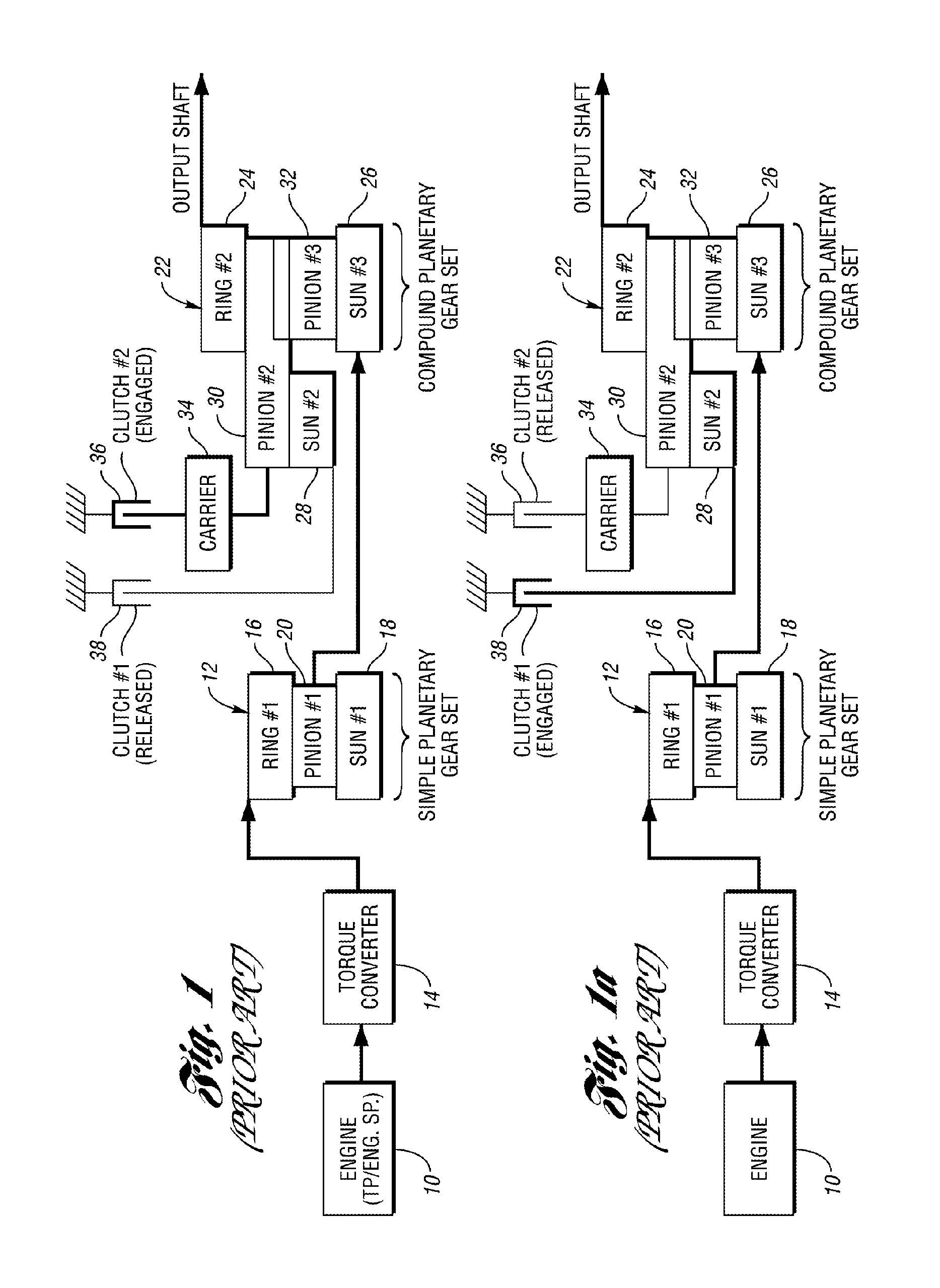
[0037]FIGS. 1 and 1a show an example of a multiple ratio geared transmission in an automotive vehicle powertrain. Although the powertrain shown in FIG. 1 includes a torque converter at the torque input side of the transmission, the present invention could be used as well in a hybrid powertrain that includes, for example, an engine and an electric motor without a torque converter. In a hybrid configuration, the power of the engine is complemented by the power generated electrically by the motor. Further, the specific gearing arrangement illustrated in FIG. 1 could be replaced by other gearing arrangements that establish multiple torque flow paths from a power source to a torque output shaft.

[0038]In the configuration of FIG. 1, an internal combustion engine is shown at 10. The torque output side of the engine is hydrokinetically coupled to a simple planetary gear set 12 of a multiple ratio transmission mechanism by a hydrokinetic torque converter 14. Torque is delivered by a torque c...


PUM


Abstract

A gear ratio shift control and control method controls gear ratio upshifts in a multiple-ratio transmission for an automotive vehicle. Pressure actuated friction elements establish torque flow paths in transmission gearing as they are selectively engaged and released. A net torque reduction at a transmission torque output shaft during an upshift event is reduced by increasing transmission input torque prior to the start of the inertia phase of the upshift event.

Description

BACKGROUND OF THE INVENTION[0001]1. Field of the Invention[0002]The invention relates to multiple ratio geared transmissions for use in an automotive vehicle powertrain and to a control strategy for effecting engagement and release of transmission friction torque establishing elements during a ratio change.[0003]2. Background Art[0004]Ratio changes in a geared automatic transmission in an automotive vehicle powertrain are achieved by engaging a so-called on-coming clutch as a so-called off-going clutch is released. The clutches, which may be referred to as transmission friction elements or brakes, establish and disestablish power flow paths from an internal combustion engine to vehicle traction wheels. During acceleration of the vehicle, the overall speed ratio, which is the ratio of transmission input shaft speed to output shaft speed, is reduced as vehicle speed increases for a given engine throttle setting. This is a ratio upshift. A downshift to achieve a higher speed ratio occu...

Claims


Application Information

Patent Timeline
Patent Type & Authority Patents(United States)
IPC IPC(8): B60W10/04F16H61/04
CPCF16H61/061F16H63/502F16H61/686F16H2200/2007Y10T477/675Y10T477/6939Y10T477/6937Y10T477/677F16H2306/42
Inventor FUJII, YUJIKRASKA, MARVIN PAULPIETRON, GREGORY MICHAELTOBLER, WILLIAM EMILORTMANN, WALTER JOSEPHRIEDLE, BRADLEY DEANCOWAN, RONALD THOMASHROVAT, DAVORIN DAVID
Owner FORD GLOBAL TECH LLC
Why Eureka
Try Eureka