
Catheter having a reinforcing mandrel

a catheter and reinforcing technology, applied in the field of medical devices, can solve the problems of ineffective transmission of axial force by the support mandrel, various drawbacks in the prior art design, etc., and achieve the effects of improving pushability, superior transmission of axial force, and rapid exchange capability

Inactive Publication Date: 2008-04-01
ABBOTT CARDIOVASCULAR
View PDF28 Cites 10 Cited by
  • Summary
  • Abstract
  • Description
  • Claims
  • Application Information

AI Technical Summary

Benefits of technology

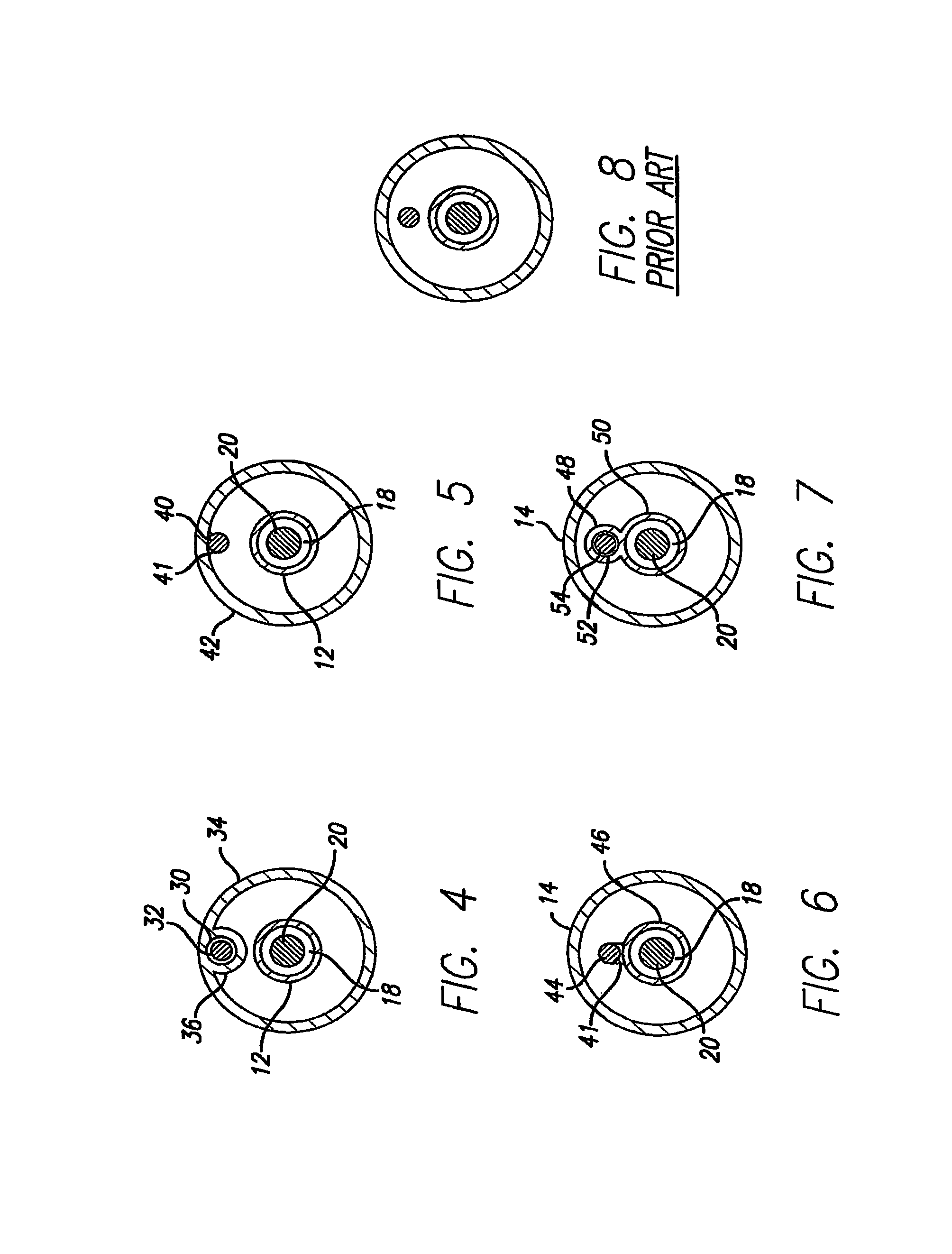
[0007]One embodiment of the catheter of the invention comprises an inner tubular member defining a guidewire lumen and an outer tubular member coaxially or eccentrically disposed about the inner tubular member to form an annular inflation lumen, with a side wall which extends longitudinally within the annular inflation lumen and which defines a mandrel lumen configured to receive a mandrel therein. In a presently preferred embodiment, the sidewall extends along at least a portion of an inner surface of the outer tubular member. However, the sidewall may alternatively extend along at least a portion of an outer surface of the inner tubular member. The reinforcement provided by the mandrel improves pushability and columnar strength of the catheter shaft formed from relatively soft materials, while inhibiting or preventing shaft kinking. This aids manufacturing by offering better bonding to balloon materials and allows greater flexibility in catheter design. These designs also permit a reduction in wall thickness to maximize the inflation lumen. The mandrel lumen may be configured to allow the mandrel to be exchanged to adjust the handling characteristics of the catheter. Thus, in one embodiment, the mandrel lumen extends to the proximal end of the shaft to facilitate mandrel exchange. Alternatively, the mandrel may be secured within the lumen, at one or more points on the mandrel.
[0009]In other embodiments, the mandrel is secured along the length of the mandrel from the proximal to the distal end thereof directly to the inner tubular member or to the outer tubular member, without a sidewall mandrel lumen. In another embodiment, the catheter has rapid exchange capabilities and generally comprises an elongated proximal tubular member having a sidewall configured to define a mandrel lumen extending longitudinally along an inner surface of the proximal tubular member. An inner tubular member overlaps the distal portion of the proximal tubular member and provides a guidewire lumen with guidewire entry and exit ports. A distal tubular member secures the adjacent portions of the proximal tubular member and the inner tubular member and carries a balloon, such as a dilatation balloon, on the distal end. The support mandrel is disposed within the mandrel lumen. Restraining the support mandrel within the lumen provides superior transmission of axial forces to improve pushability. Moreover, the dedicated lumen addresses failure concerns by allowing the catheter to be withdrawn intact in case of a mandrel fracture. When the mandrel is not confined to a dedicated lumen, a fractured end could penetrate the catheter shaft or otherwise prevent its easy removal through the tortuous vasculature.
[0010]The catheter of the invention having a mandrel has excellent crossability and trackability. The mandrel connected to the catheter shaft directly or within the dedicated mandrel lumen provides effective transmission of axial force and avoids the entanglement of the mandrel around the inner tubular member by preventing movement of the mandrel within the annular lumen. The catheter of the invention also has a low profile shaft design, and provides suitable stiffness transitions between proximal and distal portions of the catheter to improve handling and performance and minimize kinking. These and other advantages of the invention will become more apparent from the following detailed description and exemplary drawings.

Problems solved by technology

Despite these attempts, prior art designs have suffered from various drawbacks.
For example, support mandrels do not always transmit axial force effectively.

Method used


Image

  • Catheter having a reinforcing mandrel
  • Catheter having a reinforcing mandrel
  • Catheter having a reinforcing mandrel

Examples


Embodiment Construction

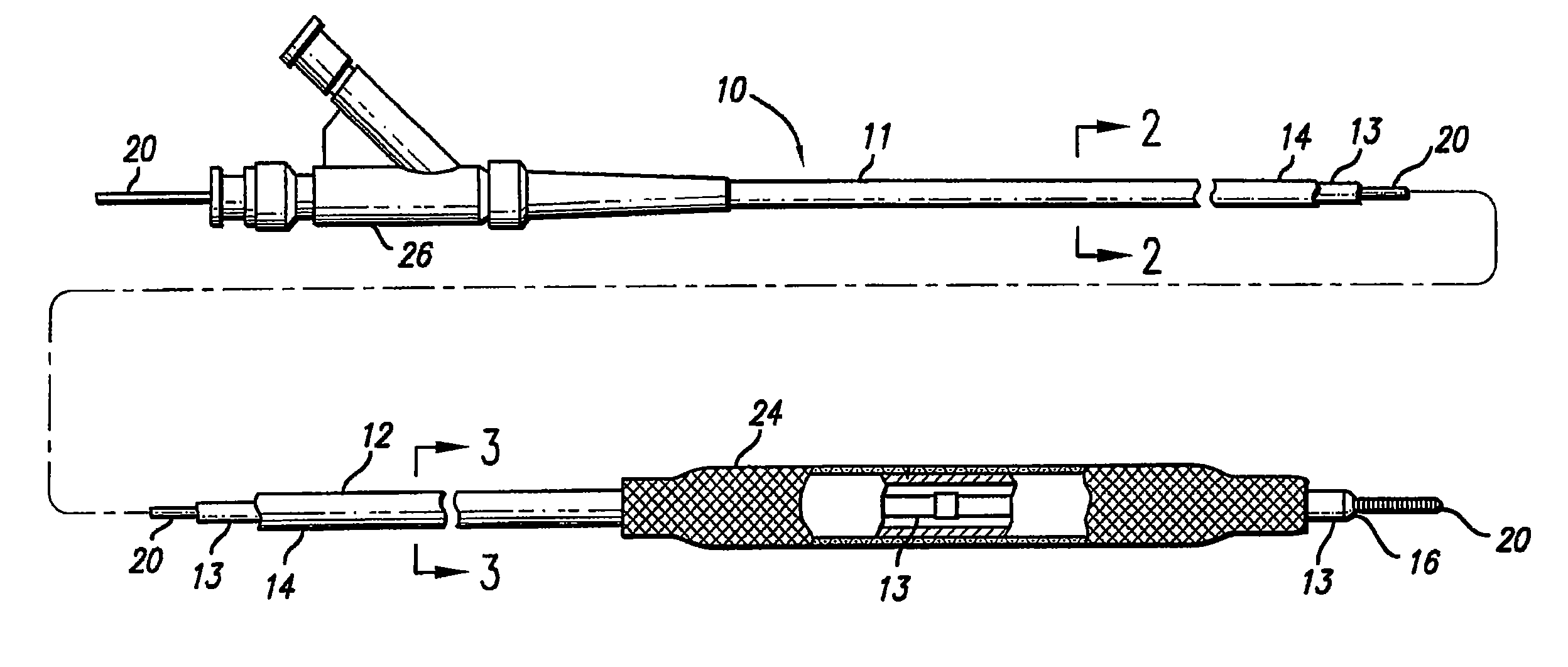
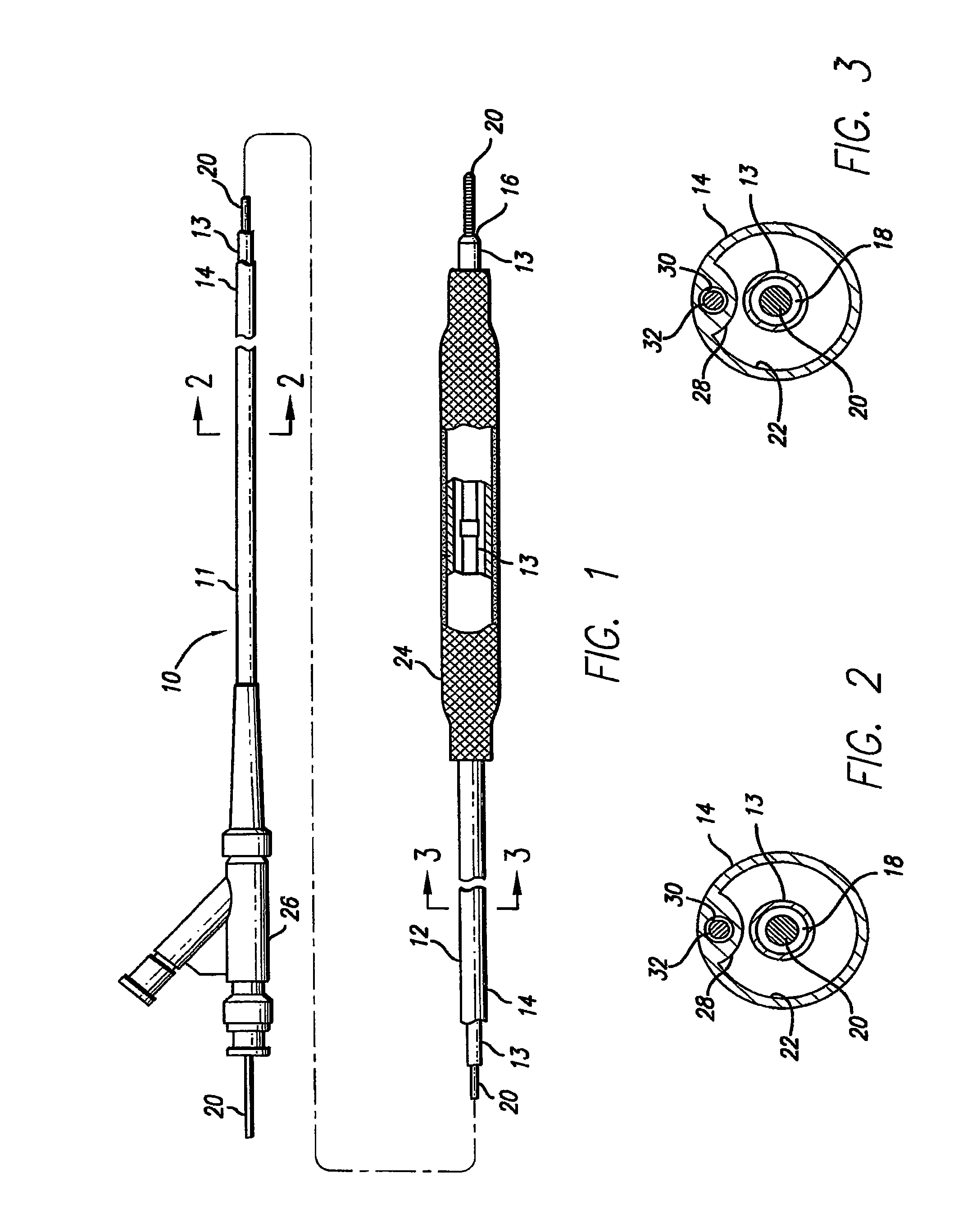
[0025]FIG. 1 illustrates a balloon catheter 10 embodying features of the invention, having a proximal shaft portion 11, a distal shaft portion 12 which is typically more flexible than proximal shaft portion 11, an inner tubular member 13, and an outer tubular member 14. Inner tubular member 13 has a guidewire port 16 at its distal end and defines a guidewire lumen 18 configured to receive guidewire 20, as best illustrated in FIGS. 2 and 3, showing transverse cross sections of the catheter shaft taken along lines 2-2 and 3-3, respectively. Outer tubular member 14 is coaxially disposed about inner tubular member 13 creating annular inflation lumen 22. A balloon 24, preferably suitable for performing an angioplasty procedure has a proximal end disposed about and secured to a distal portion of outer tubular member 14, a distal end disposed about and secured to a distal portion of the inner tubular member 13, and an interior in fluid communication with inflation lumen 22. Adapter 26 at t...


PUM


Abstract

A catheter having a mandrel secured to the catheter or constrained within a dedicated lumen. In one embodiment, the catheter has an inner tubular member and an outer tubular member with a sidewall configured to define a mandrel lumen longitudinally along an inner surface of the outer tubular member or along an outer surface of the inner tubular member. The mandrel lumen may be configured to allow the mandrel to be exchanged to adjust the handling characteristics of the catheter. The mandrel may occupy an intermediate portion of the catheter shaft, or may extend from the proximal end to within proximal or distal shaft sections of the catheter. In coronary artery applications, the mandrel is configured to support the catheter as it bends through the aortic arch and enters the coronary artery.

Description

[0001]This application is a divisional of application Ser. No. 09 / 470,519, filed Dec. 22, 1999, issued May 11, 2004 as U.S. Pat. No. 6,733,486.BACKGROUND OF THE INVENTION[0002]This invention relates to the field of medical devices, and more particularly to a balloon catheter having a reinforcing mandrel.[0003]Catheters designed for intravascular procedures such as angioplasty have a number of desirable characteristics. Such catheters must be able to transmit force along the length of the catheter shaft to allow it to be pushed through the vasculature. However, the catheter shaft must also retain sufficient flexibility to allow it to track over a guidewire through the often tortuous vasculature. Additionally, the catheter also must be able to cross stenosed portions of the vascular anatomy.[0004]To help meet the desire for a catheter having sufficient pushability and crossability, while maintaining trackability, prior art designs have supplemented polymer catheter shafts with a stiff...

Claims


Application Information

Patent Timeline
IPC IPC(8): A61M25/00
CPCA61M25/0029A61M25/0032A61M25/0054A61M2025/0004
Inventor LEE, JEONG SOOGEISER, TIMSCHENK, SANDRA K.FREEMAN, TERRYSTIGER, CHERIEL-NOUNOU, FOZAN
Owner ABBOTT CARDIOVASCULAR
Learn More