Complete knee prosthesis

a knee prosthesis and knee technology, applied in the field of complete knee prosthesis, can solve the problems of affecting the perennial function, and limiting or impossible translation movements of the femur with respect to the medial plateau, and achieve the effect of high congruen

Active Publication Date: 2008-04-01
AFRIAT JACQUES
View PDF15 Cites 45 Cited by
  • Summary
  • Abstract
  • Description
  • Claims
  • Application Information

AI Technical Summary

Benefits of technology

[0009]The purpose of this present invention is to remedy the shortcomings aforementioned of the extent complete knee prostheses, while supplying a “postero-stabilisation” prosthesis enabling to maintain high congruence between the femoral element and the medial plateau over the whole movement of the joint, while enabling perfectly controlled “roll-back” movement, and without imposing the conservation of the posterior cross ligament.

Problems solved by technology

This limited contact surface is a source of wear for the medial plateau and is therefore detrimental to the perennity thereof.
In such a case, the surface contact is maintained throughout the flexion, but, taking into account this congruence, the translation movements of the femur with respect to the medial plateau are limited or impossible.

Method used


Image

  • Complete knee prosthesis
  • Complete knee prosthesis
  • Complete knee prosthesis

Examples


Embodiment Construction

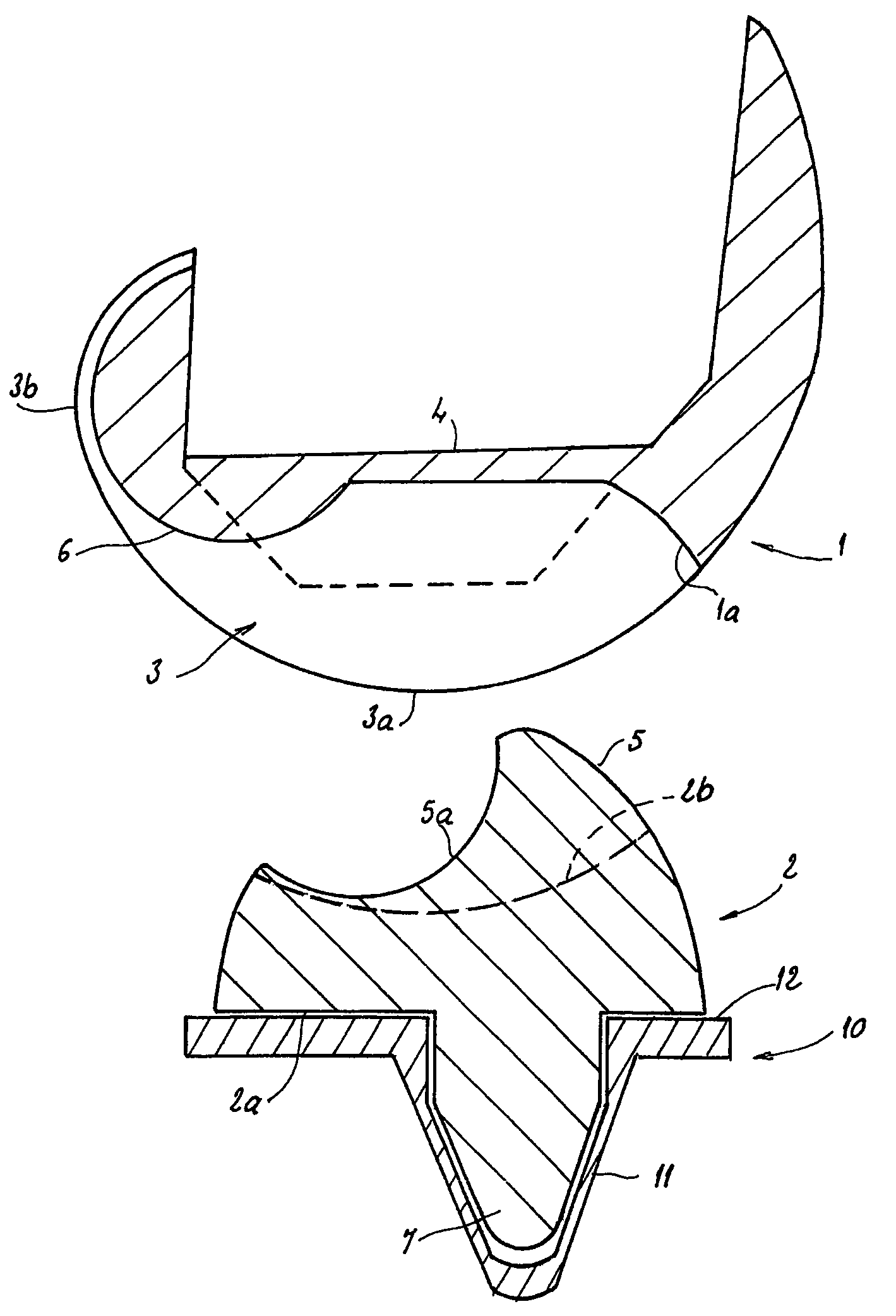
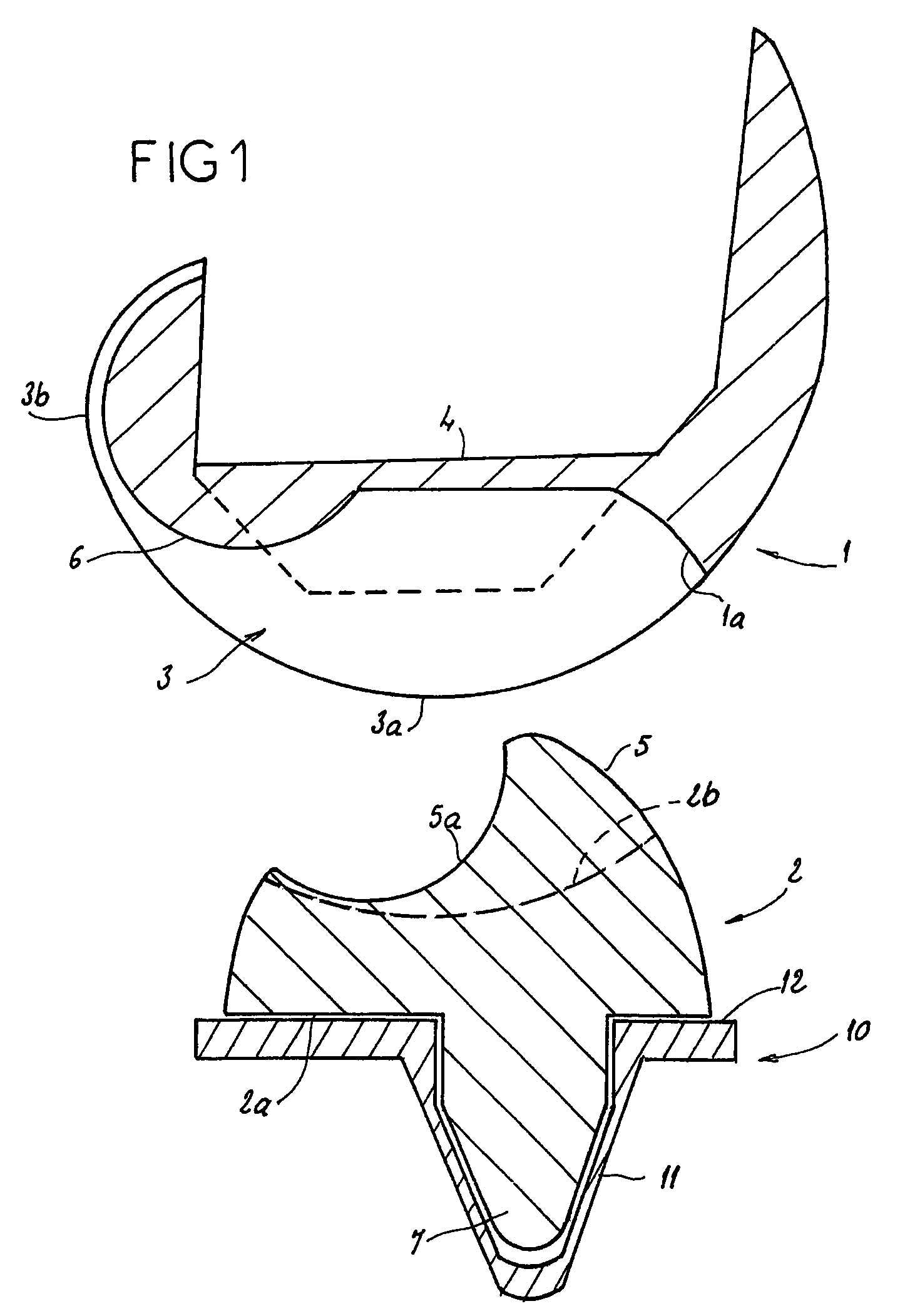
[0024]FIG. 1 represents a femoral element 1, a medial plateau 2 and a tibial seat 10 of a complete knee prosthesis. The tibial seat 10 shows a medullar keel 11 enabling its anchoring in the tibia, an upper plate 12, intended for receiving the medial plateau 2, and a cylindro-conical cavity provided in the keel 11.

[0025]The femoral element 1 has a curved shape liable to surround the distal end of the femur. It shows rounded external faces and internal facets intended for resting against the bone, after adequate resection thereof. For its anchoring to the femur, it may include a medullar rod and / or studs, not represented.

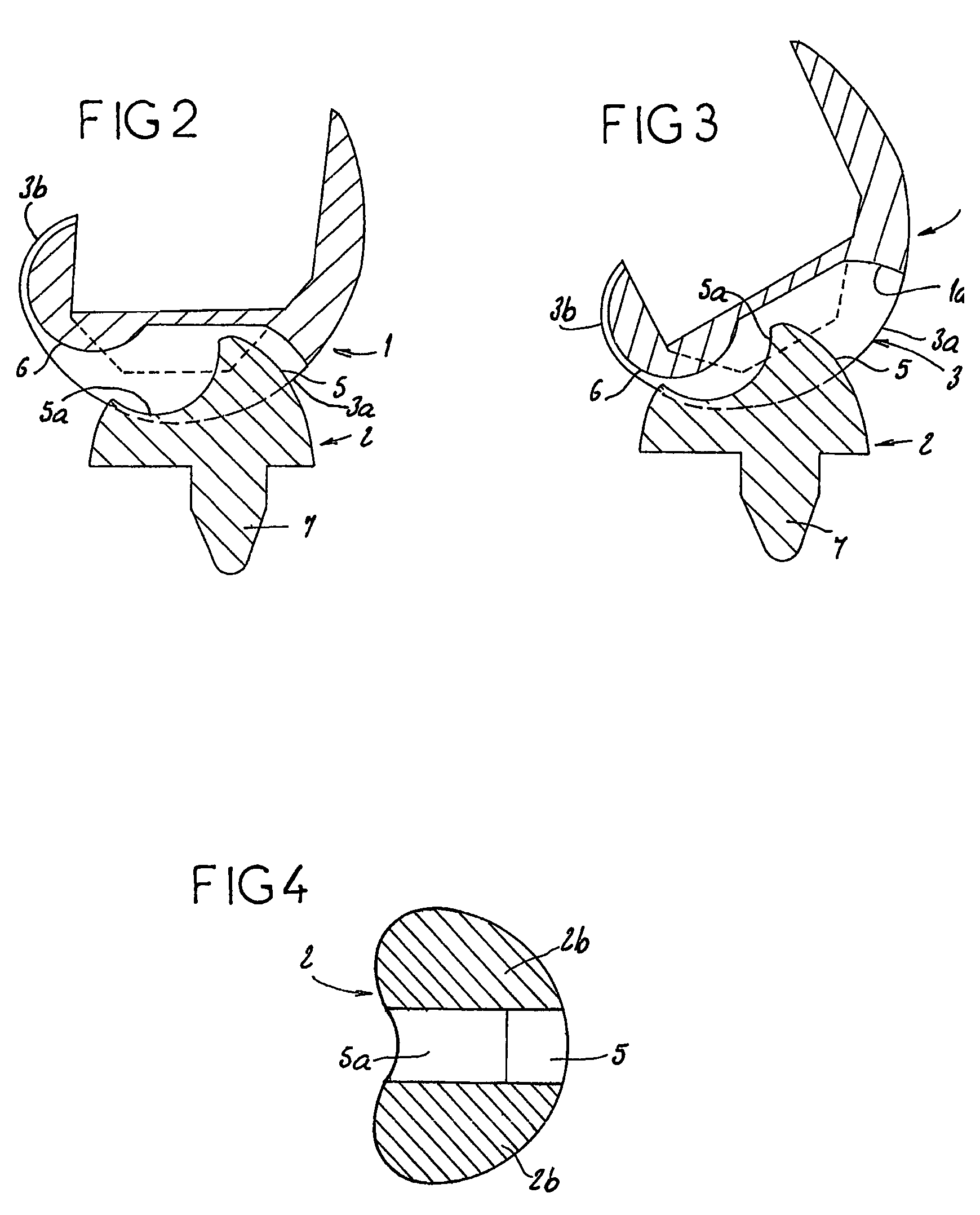
[0026]The femoral element 1 forms lateral condyles 3 having, as seen in the sagittal plane, a spiral form corresponding substantially to that of the natural condyles, i.e. with gradual reduction of their radii towards to the posterior sectors. Thus, the medial or antero-medial zone 3a of these condyles 3, which is carrying between 0 and approx. 50° of flexion (cf. FIG...


PUM


Abstract

A prosthesis whose condyles (3) have a spiral form, viewed in the saggital plane and the femoral element (1) has a medial lobe (6) with a curved surface. The medial plateau (2) has glenoid cavities (2b) for the condyles (3) and a medial prominence (5) which forms a posterior support surface (5a) against which the lobe (6) is supported in the course of movement of the joint. The glenoid cavities (2b) on the medial plateau (2) and the condyles (3) are congruent in extension and in the first part of the flexion movement of the joint. The posterior sections of the condyles (3) and the medial lobe (6) inscribe circles with the same centres and the medial lobe (6) contacts against the posterior support surface (5a) at the end of the first part of movement and then rests against the posterior support surface (5a) to perform a “roll-back”.

Description

BACKGROUND OF THE INVENTION[0001]The present invention relates to complete knee prosthesis. Such prosthesis comprises, as it is well known, a femoral element reproducing the femoral condyles, a tibial seat forming an upper support plate and a medial plateau made of a material promoting a slipping movement, notably of high density polyethylene. This medial plateau has a lower face intended for resting against the upper support plate of the tibial seat and glenoid cavities receiving the condyles of the femoral element.[0002]In a complete knee prosthesis, it is advisable that the prosthetic condyles reproduce globally the form of the natural condyles of the knee joint, to obtain good reproduction of the movement of this joint and of an adequate ligamental tension. These prosthetic condyles must therefore have, as seen in the sagittal plane, a spiral form corresponding substantially to that of the natural condyles, i.e. with gradual reduction of their radii towards the posterior sectors...

Claims


Application Information

Patent Timeline
Patent Type & Authority Patents(United States)
IPC IPC(8): A61F2/38
CPCA61F2/3868A61F2/3886
Inventor AFRIAT, JACQUES
Owner AFRIAT JACQUES
Why Eureka
Try Eureka