Voltage-sensitive oscillator frequency for rotor position detection scheme
a voltage-sensitive oscillator and rotor position technology, applied in the direction of motor/generator/converter stopper, motor/generator/converter stopper, dynamo-electric converter control, etc., can solve the problem of high noise, poor signal to noise ratio, cross-talk and other sources of noise, etc., to reduce noise sensitivity and motor current waveform characteristics, the effect of significantly reducing the sensitivity
- Summary
- Abstract
- Description
- Claims
- Application Information
AI Technical Summary
Benefits of technology
Problems solved by technology
Method used
Image
Examples
third embodiment
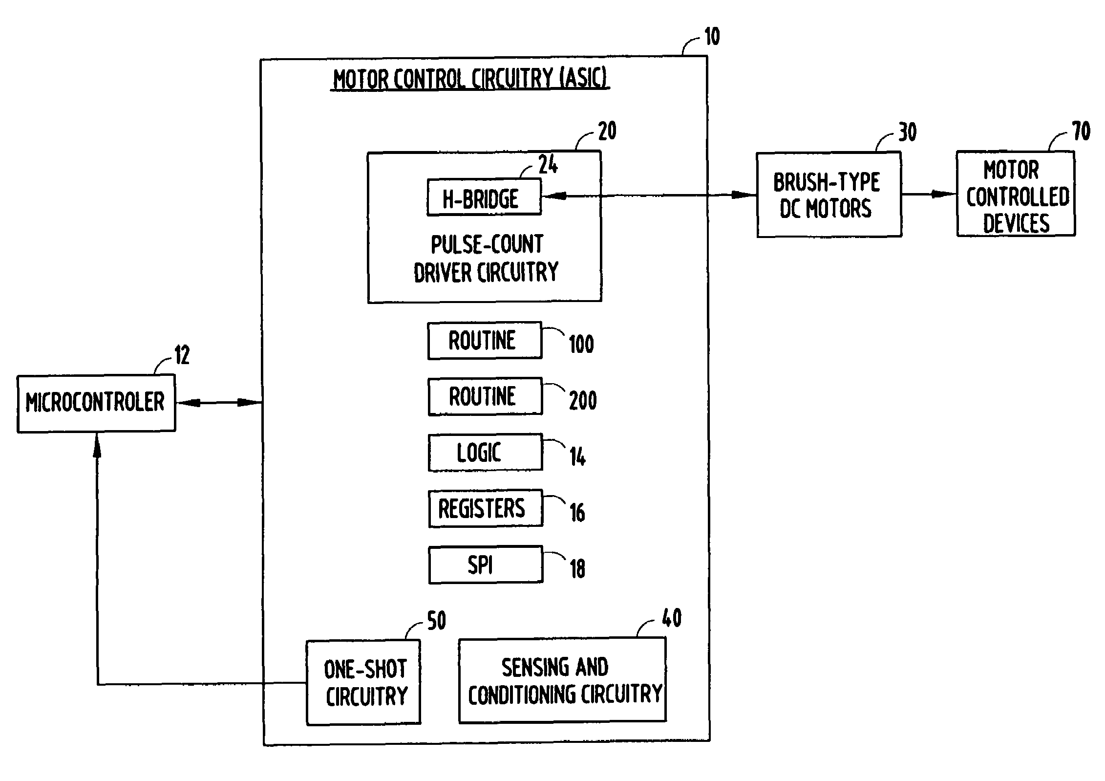
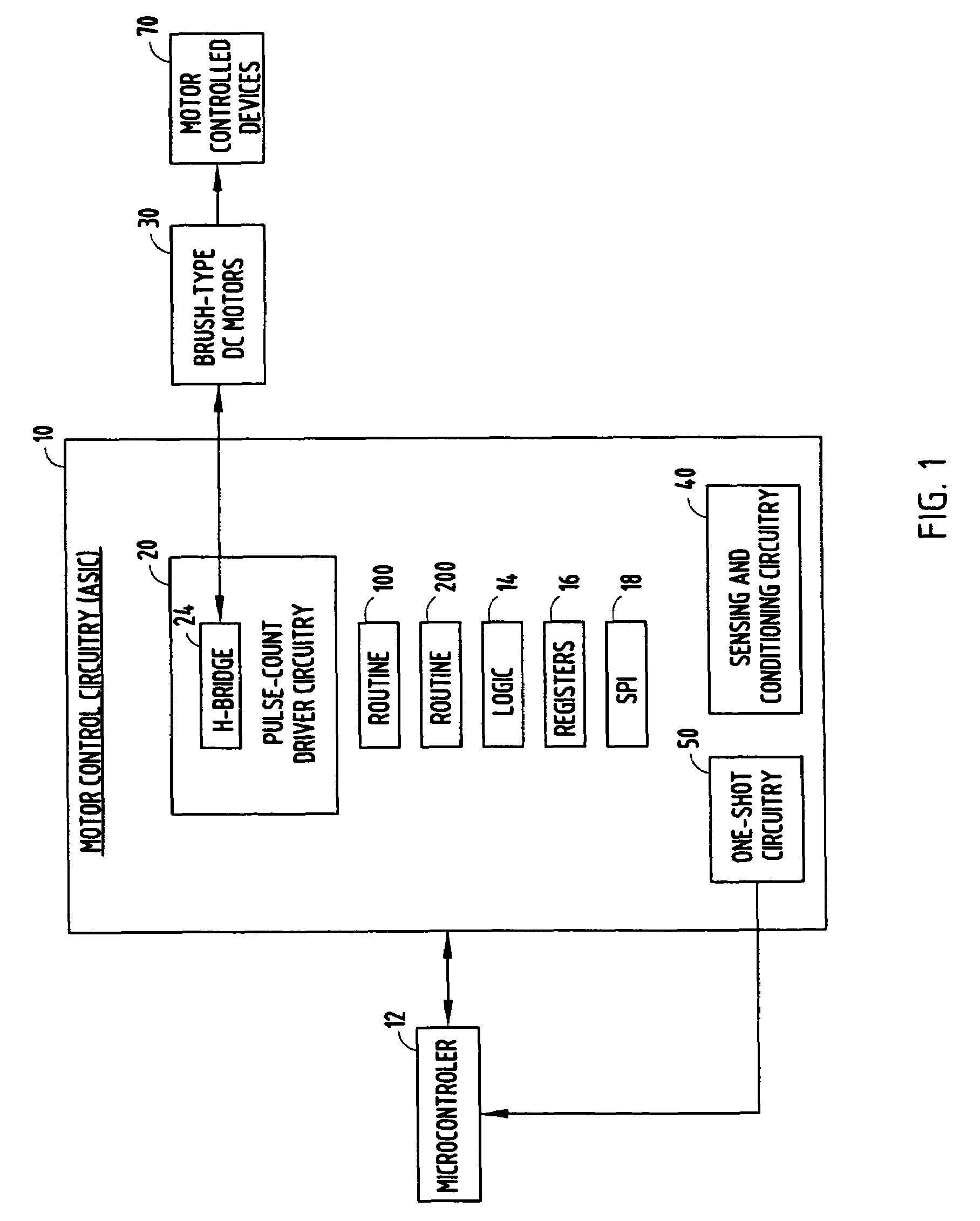
[0075]Referring to FIG. 12, an electric motor control system is generally illustrated, according to the present invention. In this embodiment, the motor control system includes brake filter circuitry 21, in addition to the other elements shown in the embodiment of FIG. 1. It should be appreciated that brake filter circuitry 21 could generally be included in the other embodiments. The motor control system according to this embodiment operates in a manner similar to the embodiment described in FIG. 1, with the added benefit that the motor shaft position detection system is improved by the addition of brake filter circuitry 21, making the system insensitive to the inductive kickback generated by shorting the motor windings when it is commanded to brake. Brake filter circuitry 21 does this by synchronizing the brake command received from microcontroller 12 with a one-shot pulse issued by one-shot circuitry 50.
[0076]FIG. 13 provides an exemplary embodiment of the brake filter circuitry 2...
fourth embodiment
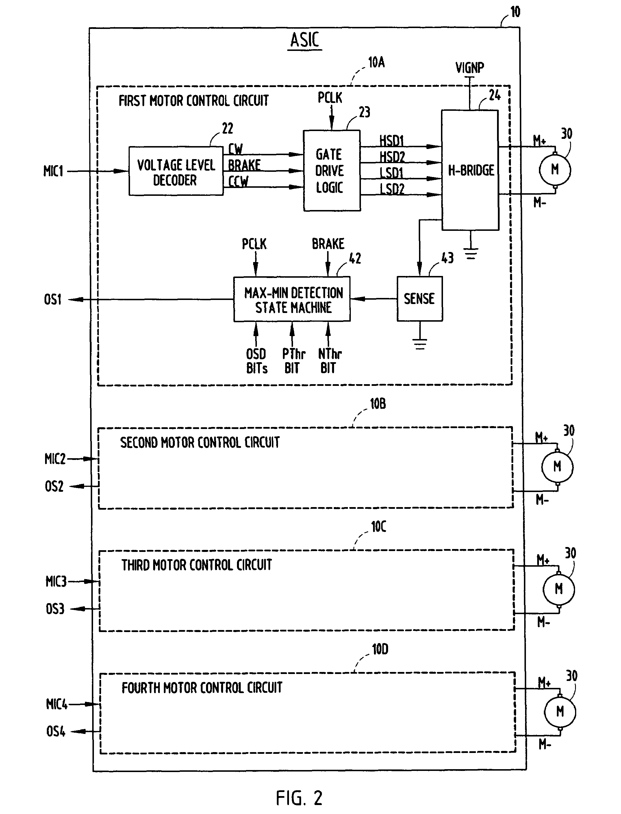
[0079]FIG. 17 illustrates exemplary circuitry for implementing the motor multiplex circuitry in the motor control system, according to the In this implementation, the pulse count motor driver shown as QPC3 includes four full H-bridge driver circuits, four high-side current sensing circuits, and four detection circuits. QPC3 and a microprocessor (corresponding to microcontroller 12 of FIG. 15) are shown connected to motor multiplex circuitry (corresponding to motor multiplex circuitry 60 of FIG. 15) that provides the capability to interface to two additional external motors (Motors 5 and 6 in FIG. 17). In this implementation, channels 3 and 4 of QPC3 are multiplexed with external driver circuitry of fifth and sixth channels, respectively. This motor control system results in the capability of controlling a total of six motors, with up to four motors able to operate simultaneously. In this exemplary configuration, only motor 3 or 5 and / or motor 4 or 6 can be operated at one time. How...
sixth embodiment
[0088]FIG. 23 generally illustrates a motor control system, in which multiple aspects of the previously discussed embodiments are used together. The combined elements include the improved sensing and detection circuitry 40 and method for more reliable detecting the rotor position of brush-type DC motors 30, an oscillator 51 connected to the battery voltage (VBATTERY) for linearly varying duration of pulses issuing from the one-shot circuitry 50 in response to signals received from sensing and detection circuitry 40, brake filter circuitry 21 for synchronizing the issuance of braking signals with pulses issued from one-shot circuitry 50, thereby eliminating another source of error in the detected rotor positions, and rotor multiplex circuitry 60 for enabling pulse count driver circuitry 20 to control and drive additional DC motors 30. In addition, motor control circuitry 10 and pulse count driver circuitry 20 are capable of receiving SPI and error signals from microcontroller 12 and...
PUM
 Abstract
Description
Claims
Application Information
 - R&D
- Intellectual Property
- Life Sciences
- Materials
- Tech Scout
- Unparalleled Data Quality
- Higher Quality Content
- 60% Fewer Hallucinations
Browse by: Latest US Patents, China's latest patents, Technical Efficacy Thesaurus, Application Domain, Technology Topic, Popular Technical Reports.
© 2025 PatSnap. All rights reserved.Legal|Privacy policy|Modern Slavery Act Transparency Statement|Sitemap|About US| Contact US: help@patsnap.com


