Solid-state imaging device driving method

a solid-state imaging and driving method technology, applied in the direction of color television details, television systems, radio control devices, etc., can solve the problems of difficult signal processing, and achieve the effects of low noise, stable potential of each pixel, and low nois

Inactive Publication Date: 2008-04-01
COLLABO INNOVATIONS INC
View PDF18 Cites 2 Cited by
  • Summary
  • Abstract
  • Description
  • Claims
  • Application Information

AI Technical Summary

Benefits of technology

[0016]According to the method of driving the solid-state imaging device, by making the low-level potential of the power supply line higher than zero potential, it is possible to prevent the entire sensor from being driven and to stabilize the potential of each pixel. Accordingly, a reproduced image with low noise can be read.
[0017]In the method of driving the solid-state imaging device, the predetermined potential may be higher than channel potentials obtained when a low level is applied to the reset transistors. By doing so, the amplifying transistors are prevented from operating in the vicinity of their respective gate regions, and thus it is possible to prevent a situation where a large number of amplifying transistors simultaneously go into operation and as a result the entire sensor is driven. Accordingly, it is possible to solve a problem that a great noise is superimposed during a horizontal blanking period, and thereby signal processing becomes difficult.
[0018]Alternatively, the predetermined potential may be higher than channel potentials obtained when a low level is applied to the transfer transistors. By doing so, it is possible to prevent a situation where because of the charges injected into the photodiodes, variations in the amount of charge to be injected occur in the photosensitive cells. Accordingly, a beautifully reproduced image with low noise can be read without causing a great noise to appear in the reproduced image.
[0019]Alternatively, the predetermined potential may be higher than channel potentials of the photodiodes. By doing so, it is possible to prevent the entire sensor from being driven and to stabilize the potential of each pixel. Accordingly, a reproduced image with low noise can be read.
[0021]Alternatively, the photosensitive region may be formed in a p-type well on an n-type substrate. By doing so, a reproduced image with low noise can be read from a solid-state imaging device having a photosensitive region formed in a p-type well on an n-type substrate.

Problems solved by technology

Accordingly, it is possible to solve a problem that a great noise is superimposed during a horizontal blanking period, and thereby signal processing becomes difficult.

Method used


Image

  • Solid-state imaging device driving method
  • Solid-state imaging device driving method
  • Solid-state imaging device driving method

Examples


Embodiment Construction

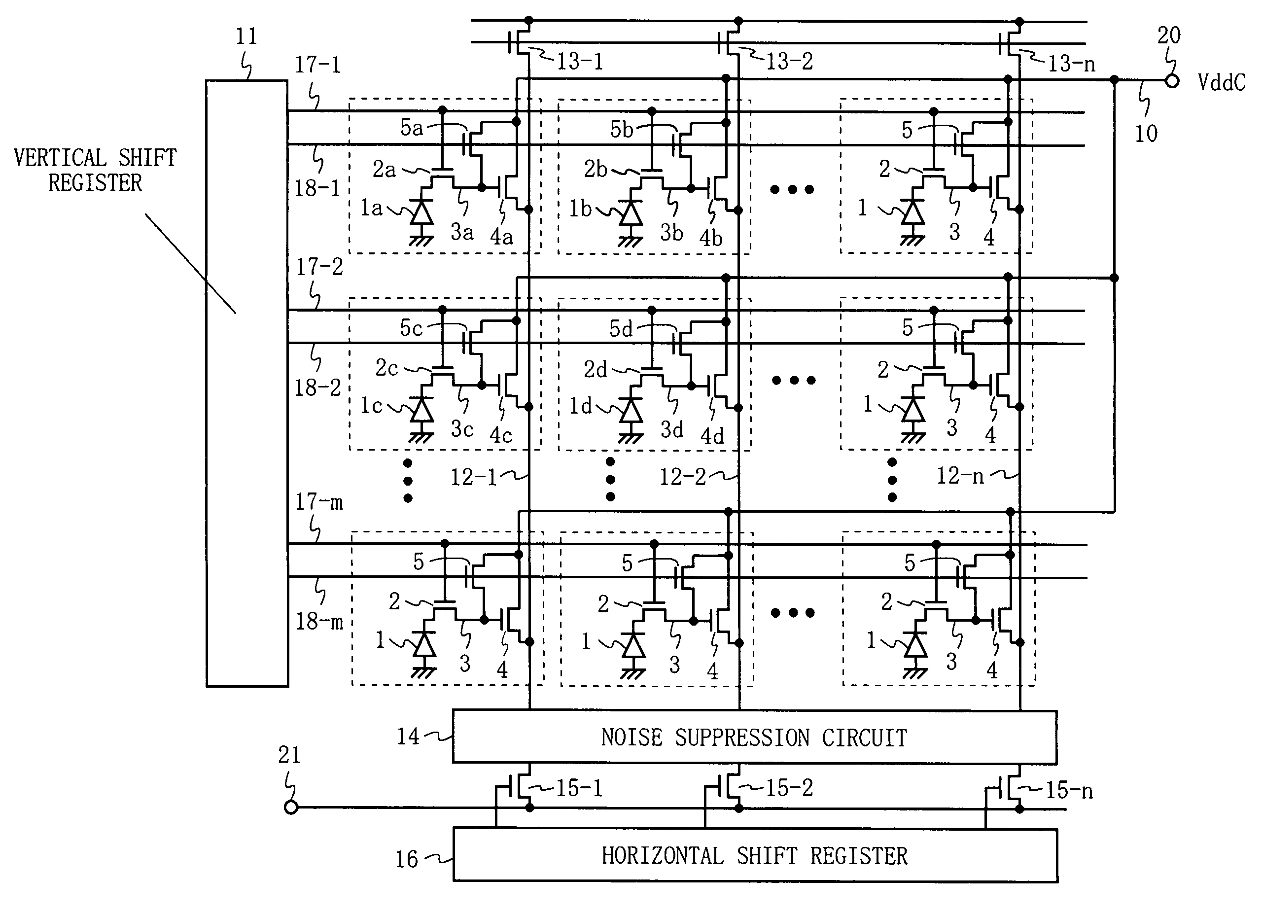
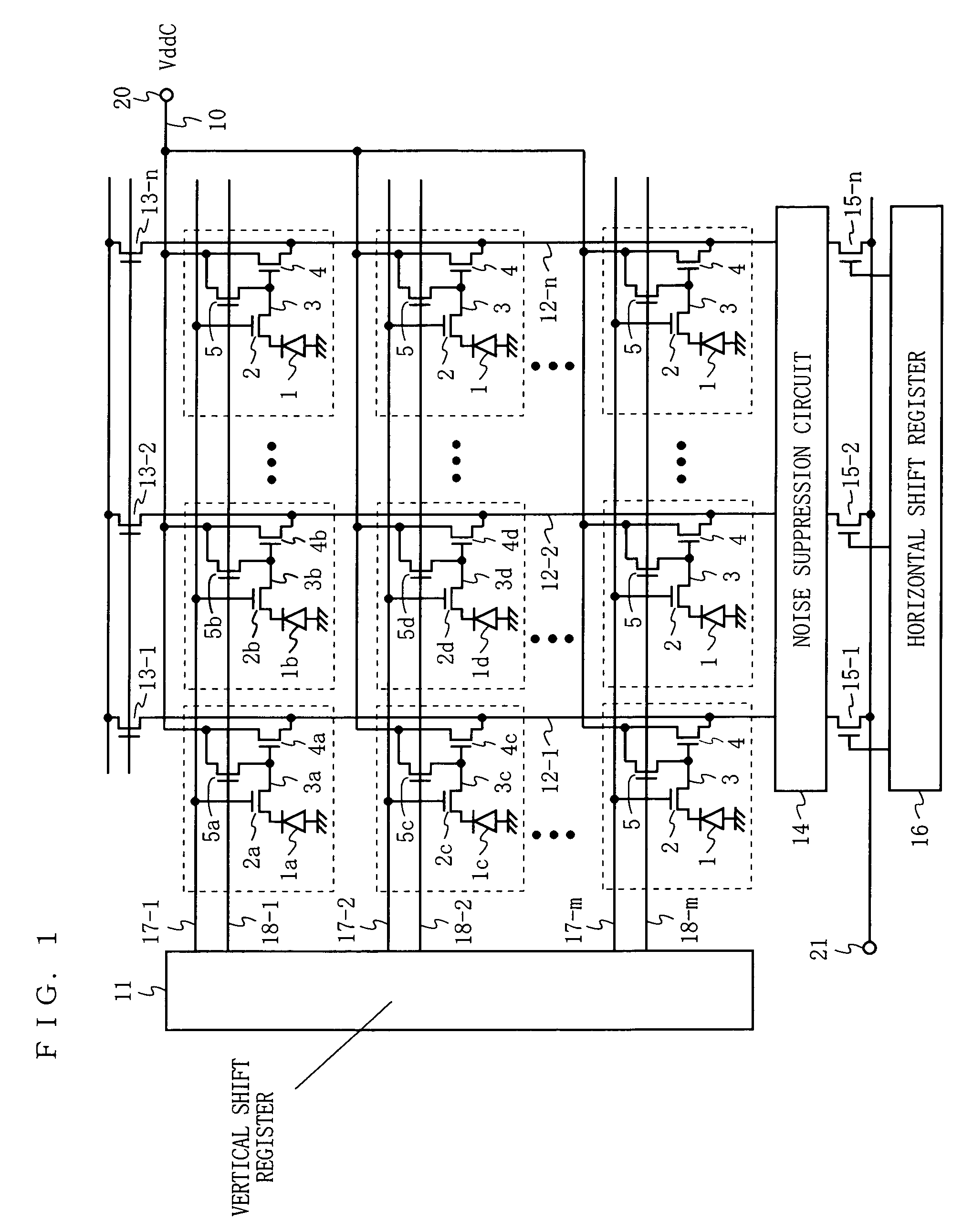
[0028]FIG. 1 is a circuit diagram of a sensor according to an embodiment of the present invention. The sensor shown in FIG. 1 has photosensitive cells (the portions surrounded by dotted-lines) arranged in an m×n matrix form; a power supply line 10; a vertical shift register 11; n vertical signal lines 12-1 to 12-n; n load transistors 13-1 to 13-n; a noise suppression circuit 14; n horizontal transistors; and a horizontal shift register 16. Each photosensitive cell includes a photodiode 1, a transfer gate 2, a floating diffusion layer portion 3, an amplifying transistor 4, and a reset transistor 5. The photosensitive cell is characterized in that it includes three transistors (the transfer gate 2, the amplifying transistor 4, and the reset transistor 5) and does not include an address transistor. The values of m and n in an actual sensor are in the order of from several tens to several thousands.

[0029]The m×n photosensitive cells are formed on a semiconductor substrate. More specific...


PUM


Abstract

Photosensitive cells each includes a photodiode (1), a transfer gate (2), a floating diffusion layer portion (3), an amplifying transistor (4), and a reset transistor (5). Drains of the amplifying transistors (4) of the photosensitive cells are connected to a power supply line (10), and a pulsed power supply voltage (VddC) is applied to the power supply line (10). Here, a low-level potential (VddC_L) of the power supply voltage has a predetermined potential higher than zero potential. Specifically, by making the low-level potential (VddC_L) higher than channel potentials obtained when a low level is applied to the reset transistors (5), or channel potentials obtained when a low level is applied to the transfer gates (2), or channel potentials of the photodiodes (1), a reproduced image with low noise is read.

Description

TECHNICAL FIELD[0001]The present invention relates to a method of driving a MOS-type solid-state imaging device for use in various apparatuses such as home video cameras, digital still cameras, and mobile phone cameras.BACKGROUND ART[0002]With reference to FIGS. 5 and 6, a conventional sensor and a driving method thereof will be described. FIG. 5 is a circuit diagram of a conventional sensor. The sensor shown in FIG. 5 has photosensitive cells (the portions surrounded by dotted-lines) arranged in a 2×2 matrix form. Each photosensitive cell includes a photodiode 51, a transfer gate 52, a floating diffusion layer portion 53, an amplifying transistor 54, a reset transistor 55, and an address transistor 56, and corresponds to one of the pixels composing an image. Note that although the following description will assume, for simplicity, that the photosensitive cells are arranged in a 2×2 matrix form, in practice, several tens to several thousands of photosensitive cells are arranged in e...

Claims


Application Information

Patent Timeline
Patent Type & Authority Patents(United States)
IPC IPC(8): H04N5/335H01L27/146H04N5/341H04N5/357H04N5/363H04N5/369H04N5/374H04N5/3745H04N5/376H04N5/378
CPCH04N5/3577H04N5/378H04N5/374H04N25/617H04N25/76H04N25/75H01L27/146
Inventor INAGAKI, MAKOTOMATSUNAGA, YOSHIYUKI
Owner COLLABO INNOVATIONS INC
Why Eureka
Try Eureka