Shifting device for a transmission

a shifting device and transmission technology, applied in the direction of gearing, mechanical control devices, gearing, etc., can solve the problems of separate pneumatic shifting devices, difficult shifting of gears with shifting devices with h-gear shifting gates, and separate actuator mechanisms of the transmission range, so as to improve the design of the invention

Inactive Publication Date: 2008-04-08
ZF FRIEDRICHSHAFEN AG
View PDF25 Cites 28 Cited by
  • Summary
  • Abstract
  • Description
  • Claims
  • Application Information

AI Technical Summary

Benefits of technology

[0036]To further enhance the design of the invention, it is possible to provide for a shift finger which could actuate a gearshift package or eng

Problems solved by technology

A disadvantage is, however, that such a gear with a shifting device with H-gear shifting gate is difficult to shift, because normally only successive gears are shifted in the same gearshift path with an H-gear shifting gate.
The disadvantage of this gear design is, however, that separate pneumatic shifting devices have to be provided for in order to be able to shift the gears the way it is usually done in an H-shifting diagram.
A disadvantage here is also the separate actuator mechanism of the transmission range.
The disadvantage of this

Method used


Image

  • Shifting device for a transmission
  • Shifting device for a transmission
  • Shifting device for a transmission

Examples


Embodiment Construction

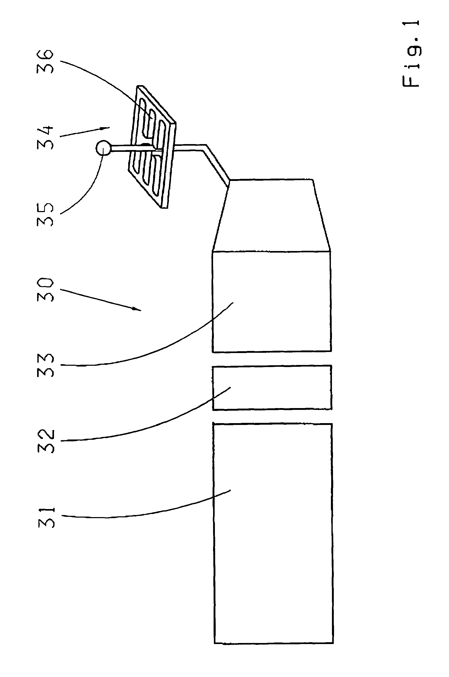
[0062]Thus, FIG. 1 shows the already known construction of a power train 30 of a vehicle with a driving motor 31, a start and shifting clutch 32 and a manual transmission 33. The transmission 33 can be operated with a manual shifting device 34 in order to set the gear transmission ratio. The shifting device 34 has a gearshift lever 35 for this purpose, which is guided in a multiple H-gearshifting gate 36. The gearshift lever 35 of this shifting device 34 or a cable system (not shown), is also connected via a gearshift linkage with a gearshifting shaft, which is inside the transmission 33 and coupled with gearshift mediums, which can change the gear transmission ratio in the transmission.

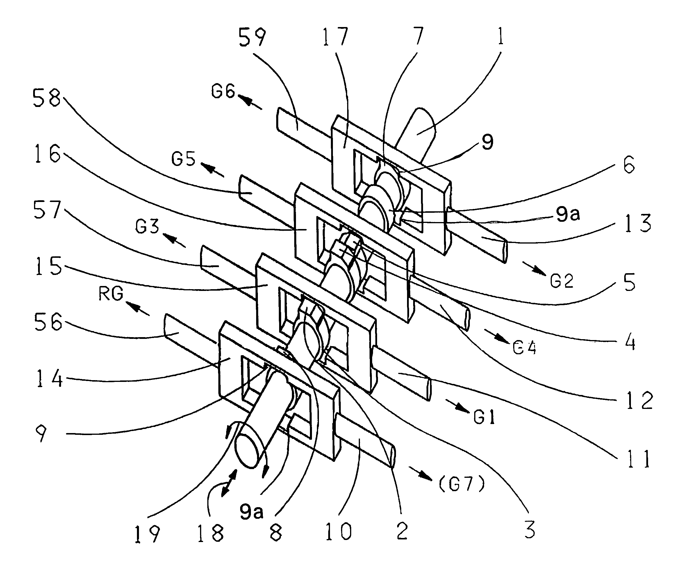
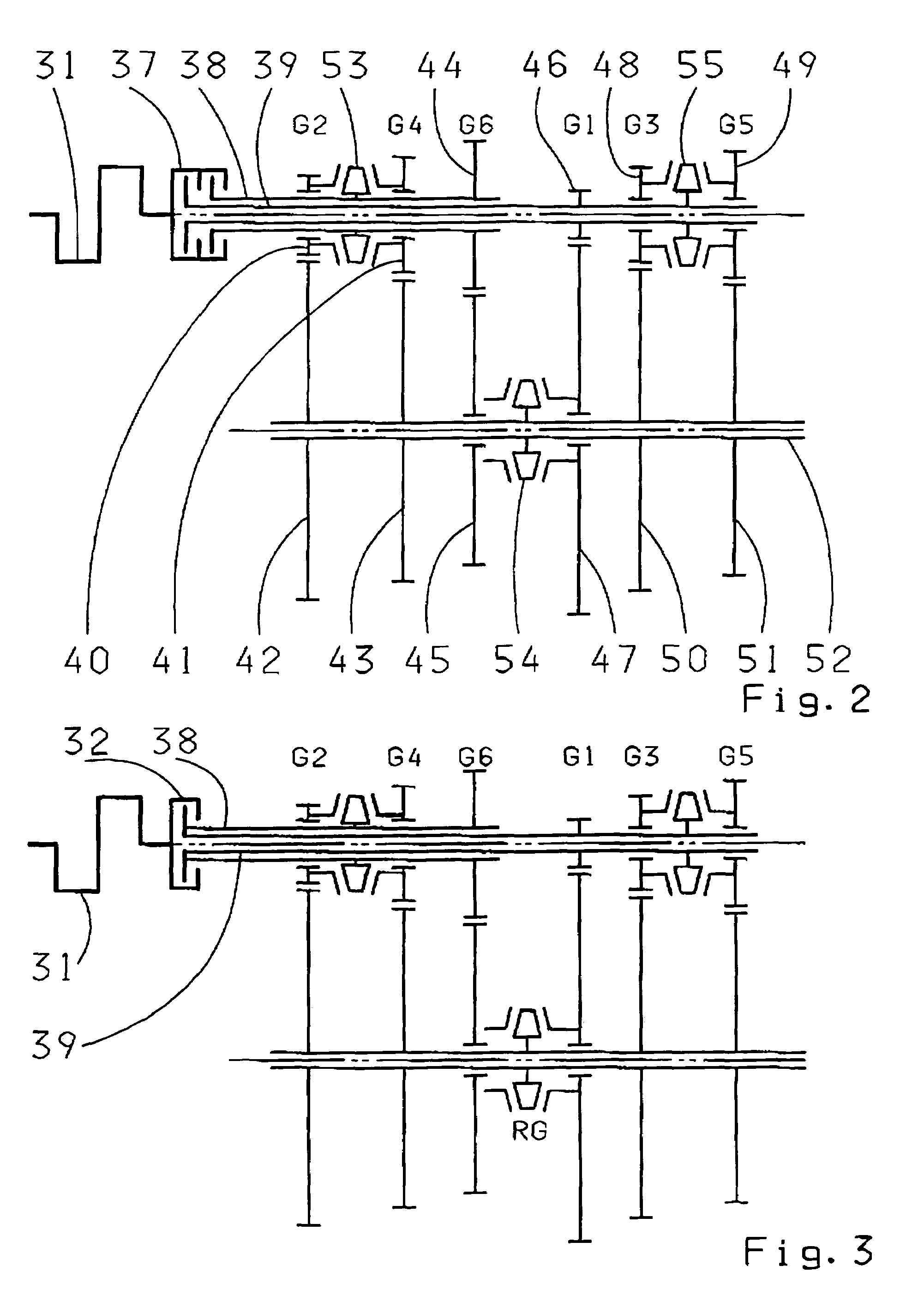
[0063]According to FIG. 1, the transmission 33, which can be operated by the shifting device 34 in order to set the gear transmission ratio, can be built as double clutch transmission (FIG. 2) or as single clutch transmission (FIG. 3). In each case, however, it is a transmission in which two gear pai...


PUM


Abstract

A shifting device for a transmission, in which at least one gearshift package is allocated to two non-successive gears and each of these gearshift packages is coupled with a gearshift lever. An H- or a multiple H-shifting diagram is allocated to the gearshift lever, in which the gears that can be selected within a gearshift path are allocated to different gearshift packages. The gearshift lever and the gearshift packages are connected to a conversion device with which a gearshift lever movement to take out a previous gear in a gearshift path causes this gear to be taken out in a first gearshift package. A gearshift lever movement for putting in the new gear in the same gearshift path, a second gearshift package puts in this new gear. The conversion device functions in such a way that the gearshift lever is coupled with an axially displaceable and radially pivotable shift finger shaft.

Description

[0001]This application is a national stage completion of PCT / EP2003 / 012585 filed Nov. 11, 2003, which claims priority from German Application Serial No. 102 53 471.3 filed Nov. 16, 2002.FIELD OF THE INVENTION[0002]The invention relates to a shifting device.BACKGROUND OF THE INVENTION[0003]Due to DE 41 37 143 A1, we are familiar with a multi-step synchronized countershaft, in which two gears each are assigned to one of several gearshift packages. These gearshift packages generally consist of sliding collars which can be moved axially, but are torsion-resistantly arranged on a gearbox shaft which, in joint action with synchronic rings that are located close to these sliding collars on the shaft, brake and accelerate loose gear wheels, and can connect rotation-resistantly with this gearbox shaft.[0004]In this transmission, the two gears (1st gear and 3rd gear or 2nd and 4th gear), which are allocated to a gearshift package, do not follow each other. This gear design has the advantage t...

Claims


Application Information

Patent Timeline
IPC IPC(8): F16H3/38F16H3/00F16H3/089F16H63/20
CPCF16H63/206F16H3/006Y10T74/19233F16H2200/0052F16H2063/025F16H2063/202Y10T74/19251Y10T74/20018Y10T74/19279Y10T74/20159Y10T74/19284Y10T74/20183Y10T74/19242Y10T74/20152Y10T74/19288Y10T74/20177Y10T74/19228F16H3/089F16H63/20
Inventor BEER, UWEDRABEK, MICHAEL
Owner ZF FRIEDRICHSHAFEN AG
Why Eureka
Try Eureka