Breather system for fuel tank

a technology for fuel tanks and breathers, which is applied in the direction of liquid fuel feeders, operating means/releasing devices of valves, machines/engines, etc., can solve the problems of difficult handling of breather pipes, complicated fuel tank structure, and increased cost, and achieves the effect of convenient handling

Inactive Publication Date: 2008-04-08
HONDA MOTOR CO LTD
View PDF16 Cites 43 Cited by
  • Summary
  • Abstract
  • Description
  • Claims
  • Application Information

AI Technical Summary

Benefits of technology

[0014]With any of the features of the present invention, the fuel supply port opened and closed by the fuel cap is provided at the central portion of the upper wall of the tank body, and the upper end of the breather pipe is located to face the central portion of the fuel supply port. Therefore, when the fuel tank is inclined, the fuel is prevented from entering the breather pipe and the fuel cap itself cannot be immersed in the fuel, thereby maintaining the sealability of the fuel supply port. Further, because the breather chamber is provided in the fuel cap, the structure of the tank body is simplified to contribute to cost reduction of the fuel tank.
[0017]With the fourth feature of the present invention, the lower end of the breather pipe extends through the bottom wall of the tank body and is connected to the canister. Therefore, the breather pipe does not extend around the outer periphery of the fuel tank and is easy to handle.

Problems solved by technology

Therefore, not only is the structure of the fuel tank itself complicated to increase the cost, but also handling of the breather pipe becomes difficult.
Another problem is in a situation where the fuel tank with the breather chamber is placed on its lower side for an extended time.

Method used


Image

  • Breather system for fuel tank
  • Breather system for fuel tank
  • Breather system for fuel tank

Examples


Embodiment Construction

[0024]The present invention will now be described by way of an embodiment of the present invention with reference to the accompanying drawings.

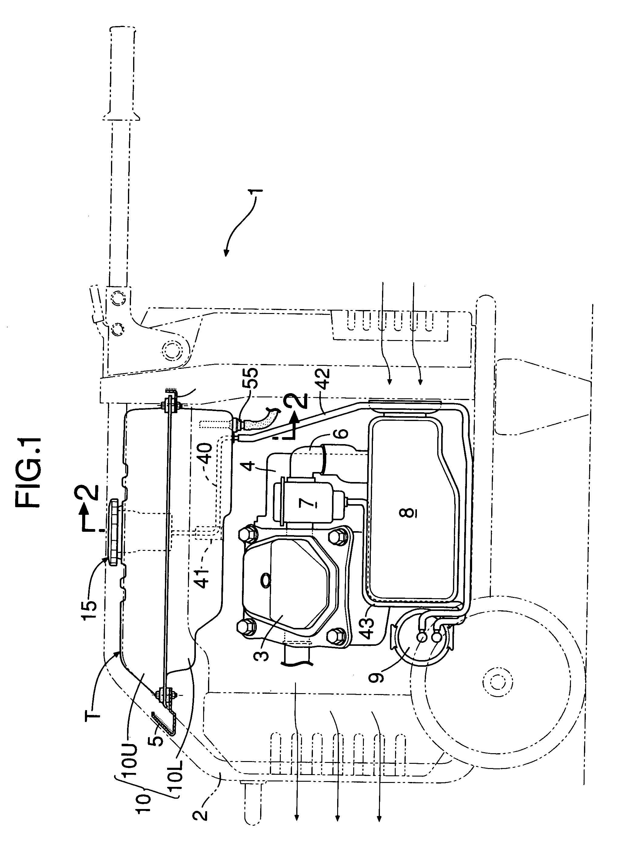
[0025]Referring to FIG. 1, a transportable engine-driven working machine 1 comprises a frame 2 formed by pipe members, and an engine 3 and a generator 4 driven by the engine 3 which are resiliently supported at a lower portion of the frame 2. A fuel tank T according to the present invention is supported at an upper portion of the frame 2 by a support bracket 5 fixed to the upper portion. A carburetor 7 is connected to a cylinder section of the engine 3. An air cleaner 8 is disposed at the lower portion of the frame 2, and is connected to the carburetor 7 through an intake pipe 6. A canister 9 is disposed on one side of the air cleaner 8 in order to absorb fuel gas evaporated in the fuel tank T.

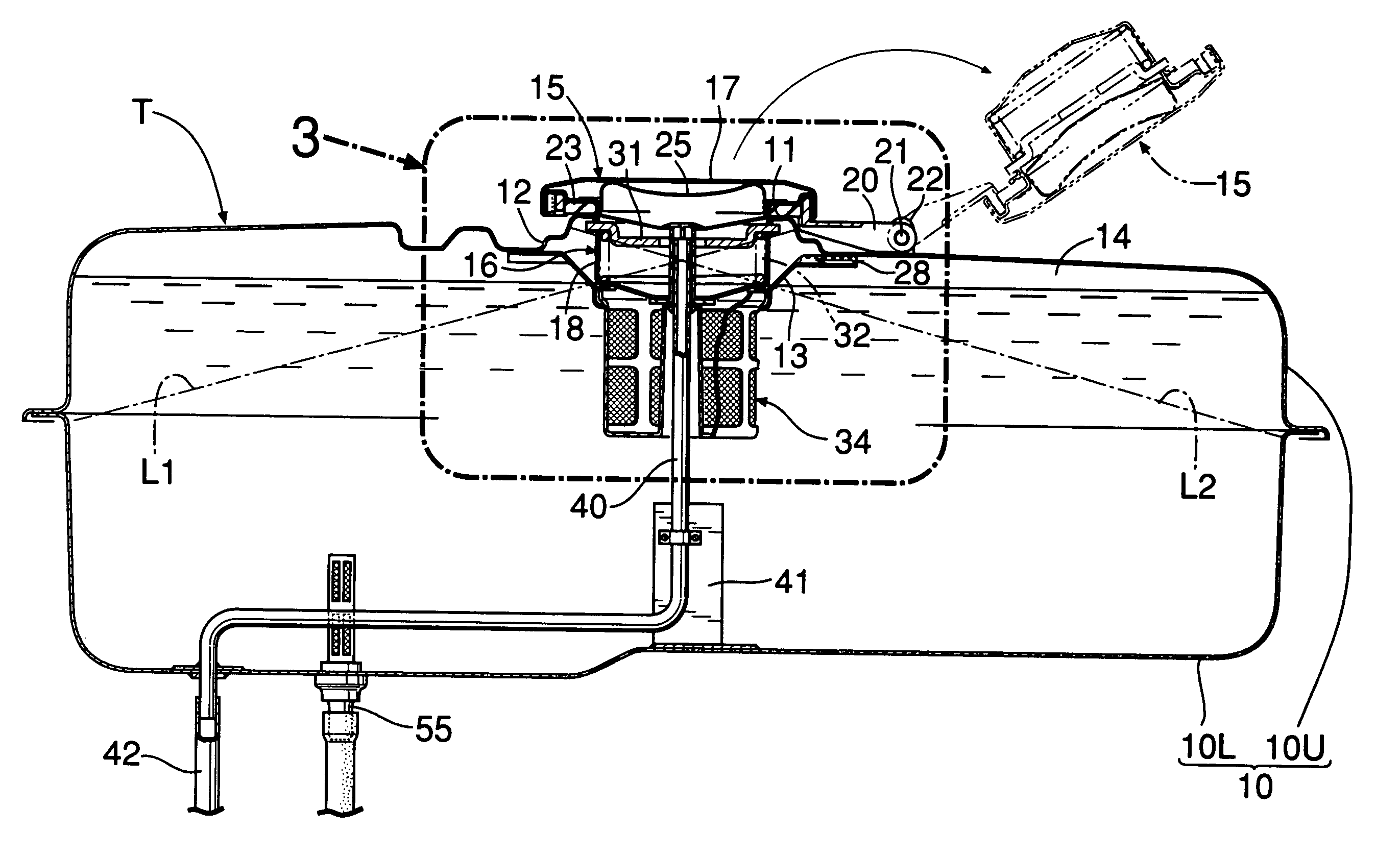
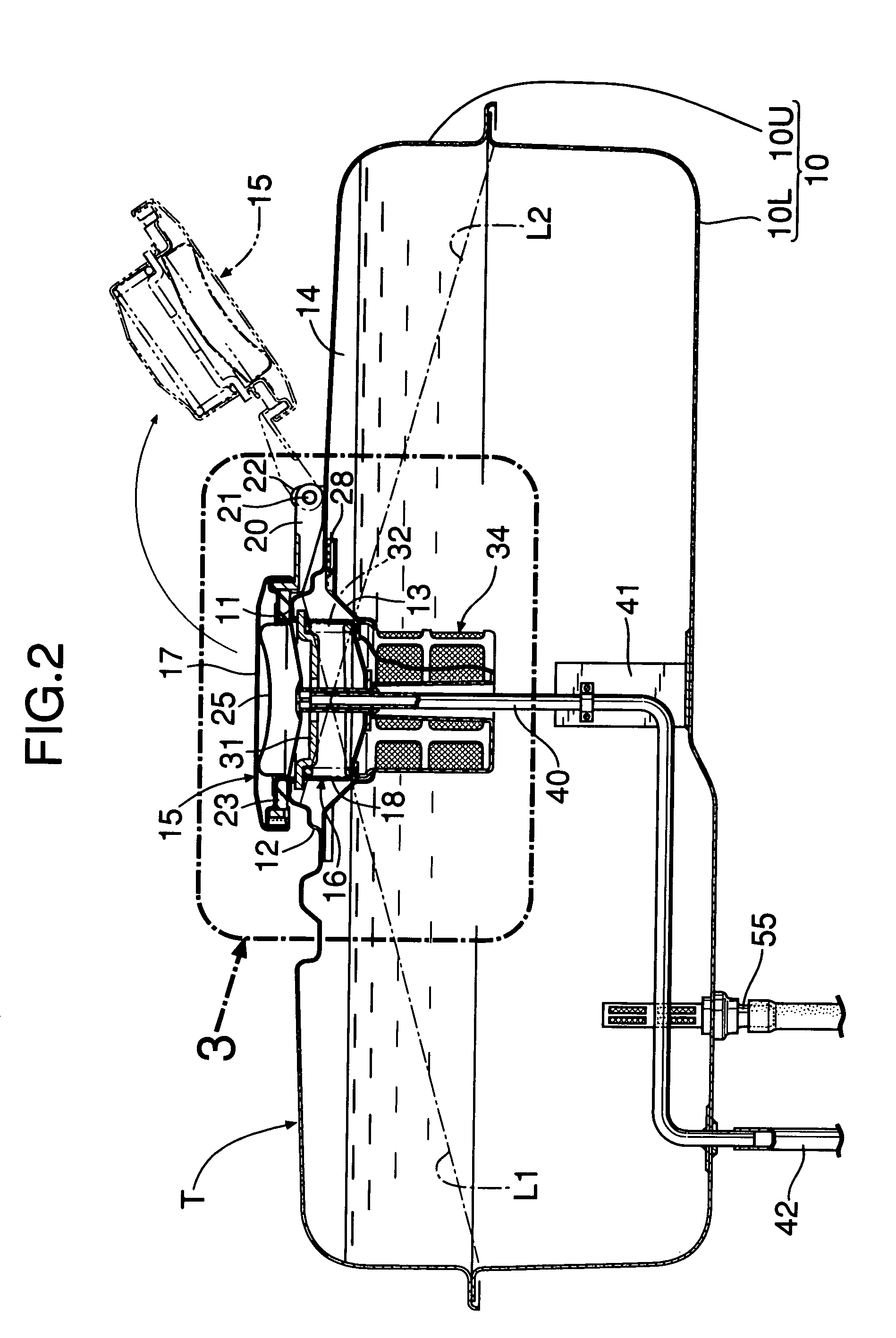
[0026]The structure of the fuel tank T will be described below with reference to FIGS. 2 to 5.

[0027]The fuel tank T has a tank body 10 formed into a ve...


PUM


Abstract

In a breather system for a fuel tank having a tank body, a fuel supply port opened and closed by a fuel cap provided in a central portion of an upper wall of the tank body, wherein an upper end of a breather pipe is located to face a central portion of a fuel supply port. When the fuel supply port is closed by the fuel cap, a breather chamber is formed in the fuel cap and the breather chamber communicates with the breather pipe. Thus, when the fuel tank is inclined, fuel is prevented from entering the breather pipe, and the fuel supply port is not immersed in the fuel, thereby maintaining the sealability of the fuel supply port.

Description

RELATED APPLICATION DATA[0001]The present invention is based upon Japanese priority application No. 2005-22402, filed Jan. 31, 2005, which is hereby incorporated in its entirety herein by reference.BACKGROUND OF THE INVENTION[0002]1. Field of the Invention[0003]The present invention relates to a breather system for a fuel tank, and more particularly to a breather system for a fuel tank for supplying fuel to an engine of an engine-driven working machine.[0004]2. Description of the Related Art[0005]A fuel tank for supplying fuel to an engine of an engine-driven working machine, generally comprises a breather system for performing breathing action between the outside and an air chamber provided in an upper portion of the fuel tank in order to maintain a constant pressure in the fuel tank.[0006]In a conventional breather system, as disclosed in Japanese Utility Model Application Laid-open No. 62-196791, a breather cap 2 is mounted on one side of an upper wall of a fuel tank 1 apart from...

Claims


Application Information

Patent Timeline
Patent Type & Authority Patents(United States)
IPC IPC(8): F02M37/20
CPCF16K24/042F16K31/20F02B63/04Y10T137/86324
Inventor KAKOO, HIROMI
Owner HONDA MOTOR CO LTD
Why Eureka
Try Eureka