Wind power generation device

a wind power generation and wind power technology, applied in the direction of machines/engines, stators, liquid fuel engines, etc., can solve the problems of reducing the entire pressure area, and achieve the effects of reducing pressure, preventing the tip swaying, and increasing the wind speed in the du

Inactive Publication Date: 2008-04-08
BABA TECHN LAB
View PDF8 Cites 26 Cited by
  • Summary
  • Abstract
  • Description
  • Claims
  • Application Information

AI Technical Summary

Benefits of technology

[0006]According to the invention, when wind from the front to the rear of the duct is created, the reduced pressure area can be produced while generation of swirl is prevented at the rear of the duct. Thus, bringing wind into the duct by the reduced pressure area can increase the wind speed in the duct while eliminating the flow of wind from the front to the inside of the duct being prevented by the swirl at the rear of the duct.
[0015]Therefore, according to the wind power generation device of the present invention, in addition to the above described items (1) to (3), power generation efficiency can be maximized through: (4) maximizing the speed of the wind in the duct by maximizing the degree of reduced pressure in the reduced pressure area at the rear of the duct.

Problems solved by technology

On the other hand, according to the inventor's findings, the tip of the reduced pressure area is tapered and unstable and is apt to sway in a diametrical direction of the duct, and thus large sway resulting from changes in directions of wind near the tip causes the entire reduce pressure area to disappear.

Method used


Image

  • Wind power generation device
  • Wind power generation device
  • Wind power generation device

Examples


Embodiment Construction

[0020]An embodiment of a wind power generation device according to the present invention will be described with reference to the drawings.

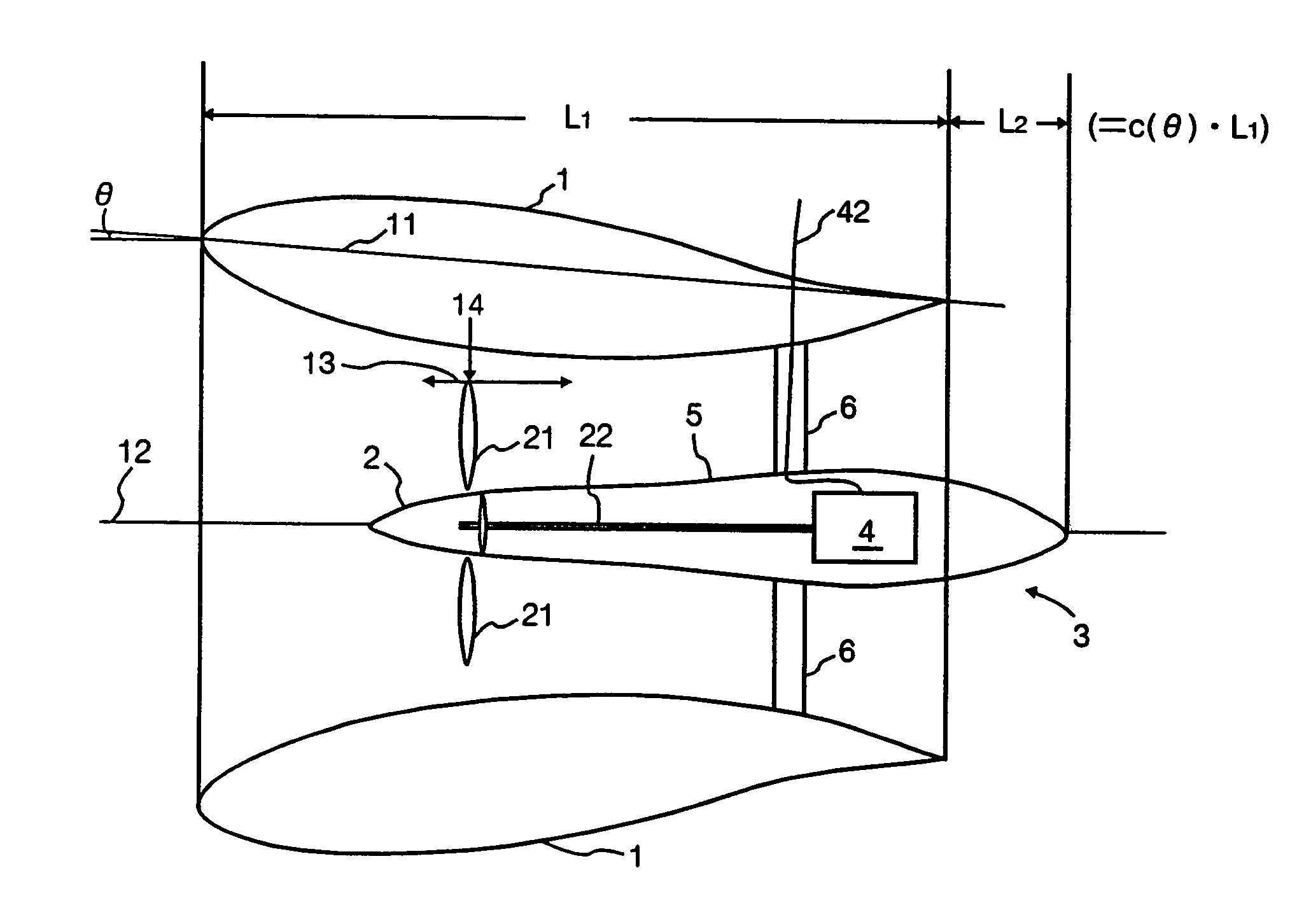
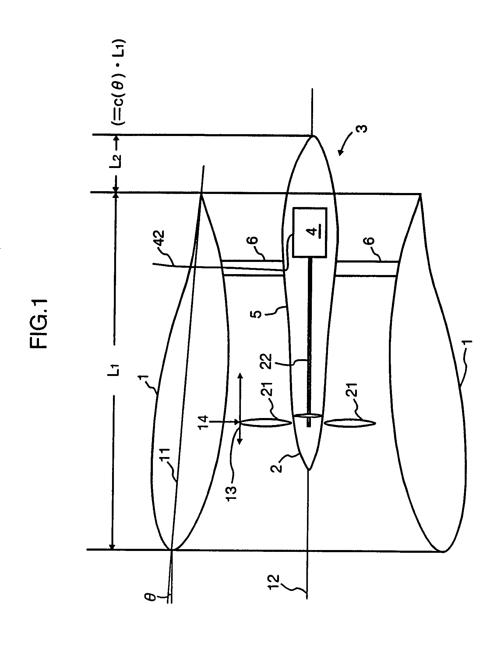
[0021]The wind power generation device in FIG. 1 comprises: a substantially cylindrical duct 1; an impeller 2 having a plurality of blades 21 protruding outward and rotatable around a duct axis x; and a nacelle 5 that constitutes a streamlined pencil body 3 together with the impeller 2 and houses a generator 4 that uses torque of the impeller 2 transmitted via a rotational axis 22. The nacelle 5 is secured to the duct 1 by a post 6 protruding from an inner wall of the duct 1. Power generation energy from the generator 4 is supplied to the outside via a lead 42 passing through the post 6 and the duct 1.

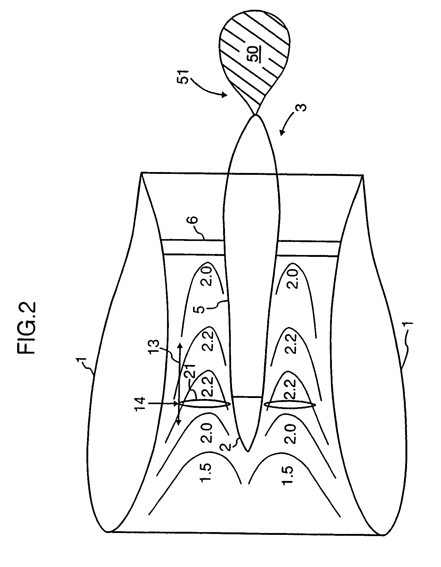
[0022]The duct 1 has a side wall with a wing section. This is intended to produce a reduced pressure area at a rear of the duct 1 and prevent generation of swirl at the rear of the duct 1 as described later. As the wing section of the side wall of th...


PUM


Abstract

A wind power generation device capable of improving power generation efficiency is provided. The wind power generation device according to the present invention comprises: a substantially cylindrical duct 1 having a side wall with a substantially wing section; an impeller 2 rotatable around an axis of the duct 1; and a nacelle 5 that constitutes a streamlined pencil body 3 together with the impeller 2 and houses a generator 4 that uses torque of the impeller 2. The duct 1 has the side wall with the wing section so as to be able to produce a reduced pressure area at a rear of the duct and prevent generation of swirl at the rear of the duct 1. The pencil body 3 is provided so that a tip thereof is placed in the duct 1 and a rear end thereof protrudes from a rear end of the duct 1 so as to be close to a tip of the reduced pressure area produced at the rear of the duct 1. Blades 21 of the impeller 2 are provided in a maximum wind speed area 13 in the duct 1.

Description

TECHNICAL FIELD[0001]The present invention relates to a wind power generation device comprising: a substantially cylindrical duct having a side wall with a substantially wing section; an impeller having a plurality of blades protruding outward and rotatable around a duct axis; and a nacelle that constitutes a streamlined pencil body together with the impeller and houses a generator that uses torque of the impeller.BACKGROUND ART[0002]Some wind power generation devices similar to the above described wind power generation device have been proposed in view of efficient rotation of an impeller for improving power generation efficiency (see Japanese Utility Model Laid-Open No. 56-74871).[0003]The inventor of the present application has studied airflow near a wind power generation device and found that power generation efficiency is susceptible to improvement.[0004]Thus, the present invention has an object to provide a wind power generation device capable of improving power generation eff...

Claims


Application Information

Patent Timeline
Patent Type & Authority Patents(United States)
IPC IPC(8): F03D7/02F03D1/04
CPCF03D1/04F05B2240/133Y02B10/30Y02E10/72F03D80/80Y10S415/908
Inventor BABA, YOSHIMI
Owner BABA TECHN LAB
Why Eureka
Try Eureka