
Roller type one-way clutch and roller for the roller type one-way clutch

a roller type technology, applied in the direction of clutches, friction clutches, clutches, etc., can solve the problems of continuous slippage, the meshing side of the roller type one-way clutch does not normally function, and the roller type one-way clutch does not normally mesh, so as to improve the meshing performance and ensure the effect of meshing reliability. , the effect of further increasing

Active Publication Date: 2008-04-15
NSK WARNER
View PDF5 Cites 3 Cited by
  • Summary
  • Abstract
  • Description
  • Claims
  • Application Information

AI Technical Summary

Benefits of technology

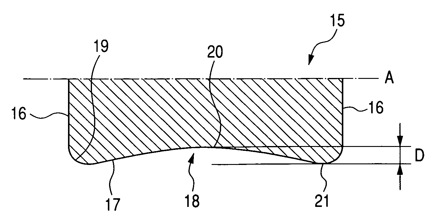
This design improves meshing performance and reliability at lower temperatures, ensuring effective torque transmission and durability by ensuring the recess depth is within optimal limits for oil film shearing and elastic deformation.

Problems solved by technology

However, when for example, the one-way clutch is used under a very low temperature environment (−20° C. to −40° C.) and the viscosity of ATF in an automatic transmission becomes high, it may happen that the roller type one-way clutch does not normally mesh during meshing engagement from idle rotation, but continuously slips.
This leads to the problem that the meshing side of the roller type one-way clutch does not normally function.
For the roller type one-way clutch to mesh, the oil film between the roller and a raceway surface during idle rotation must be sheared and metals must completely contact with each other, but under a very low temperature, there has been the undesirable possibility that the roller continues to slip on the oil (ATF) made high in viscosity.
This is because the oil film cannot be cut by the roller.

Method used


Image

  • Roller type one-way clutch and roller for the roller type one-way clutch
  • Roller type one-way clutch and roller for the roller type one-way clutch
  • Roller type one-way clutch and roller for the roller type one-way clutch

Examples


Embodiment Construction

[0022]The present invention will hereinafter be described in detail with reference to the drawings. The embodiments hereinafter described are illustrative of the present invention and of course, do not restrict the present invention thereto. Also, throughout the drawings, like portions are represented by like reference characters.

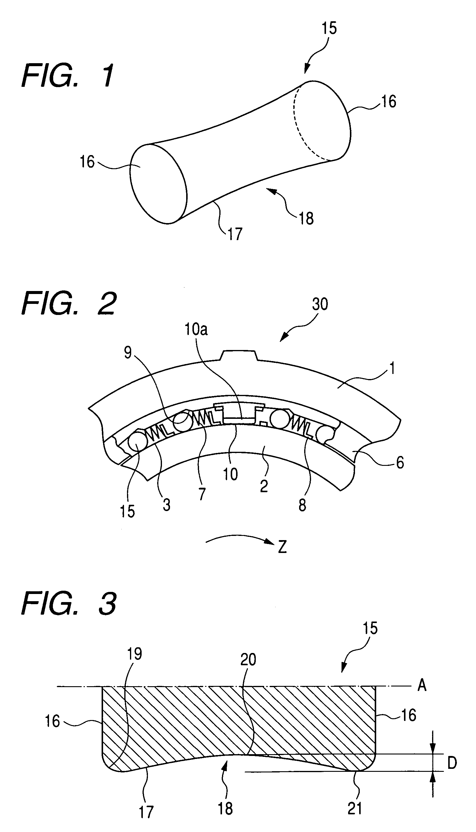
[0023]FIG. 2 is a partly broken-away front view showing an inner peripheral cam roller type one-way clutch 30 according to an embodiment of the present invention. In the ensuring description, for the simplification of description, the “roller type one-way clutch” will be simply referred to as the “one-way clutch”.

[0024]The one-way clutch 30 comprises an outer ring 1, an inner ring 2 disposed concentrically with the outer ring 1, a plurality of roller members, i.e., rollers 15 disposed between the outer peripheral raceway surface 3 of the inner ring 2 and the inner peripheral cam surface 9 of the outer ring 1, a pad rod 10 for effecting the centering of the ...


PUM


Abstract

A roller type one-way clutch includes an outer ring and an inner ring disposed concentrically with each other for rotation relative to each other, the outer ring having an axially extending annular inner peripheral cam surface, the inner ring being disposed in the outer ring and having an annular outer peripheral raceway surface, and a plurality of rollers disposed between the outer ring and the inner ring for transmitting torque between the outer peripheral raceway surface and the inner peripheral cam surface. The rolling surface of each of the rollers has a recess depressed toward the axis thereof over the entire circumference thereof. In an alternative arrangement, an axially extending annular inner peripheral raceway surface is provided on the outer ring and an annular outer peripheral cam surface is provided on the inner ring.

Description

BACKGROUND OF THE INVENTION[0001]1. Field of the Invention[0002]This invention relates to a roller type one-way clutch for use as a part of torque transmission, back stop or the like, for example, in the driving apparatus of an automobile, an industrial machine or the like, and more particularly to an improvement in a roller for the roller type one-way clutch.[0003]2. Related Background Art[0004]Generally, a roller type one-way clutch comprises an outer ring, an inner ring disposed concentrically with the outer ring, a plurality of rollers disposed between the outer peripheral surface of the inner ring and the inner peripheral cam surface of the outer ring for transmitting torque, a pad bearing having a U-shaped cross section for effecting the centering of the outer ring and the inner ring and also, guiding the rollers, a spring being in contact with the idle rotation side of the rollers, a mounting plate for the spring, etc.[0005]In such a construction, the one-way clutch is design...

Claims


Application Information

Patent Timeline
Patent Type & Authority Patents(United States)
IPC IPC(8): F16D41/066F16D13/74F16D41/06
CPCF16D41/066
Inventor OGATA, HIROFUMIHASEBE, TOMONOBUOHISHI, HIDEHARU
Owner NSK WARNER
Learn More