
Plastic bottle with handle

a plastic bottle and handle technology, applied in the direction of rigid containers, packaging, transportation and packaging, etc., can solve the problems of waste of plastic, large squeezing force, waste of plastic containers, etc., and achieve the effect of efficiently reducing volum

Inactive Publication Date: 2008-04-15
YOSHINO KOGYOSHO CO LTD
View PDF41 Cites 29 Cited by
  • Summary
  • Abstract
  • Description
  • Claims
  • Application Information

AI Technical Summary

Benefits of technology

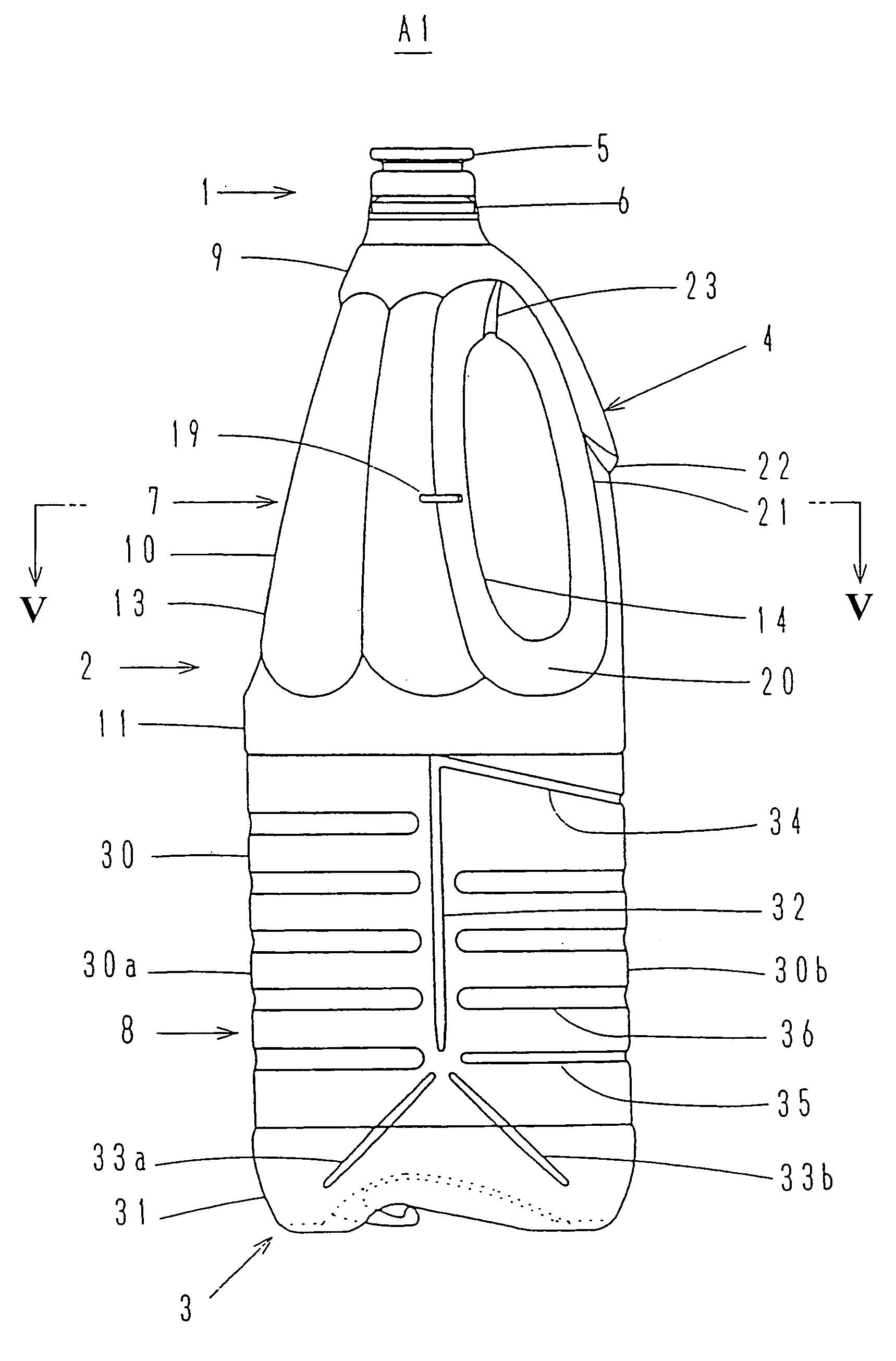
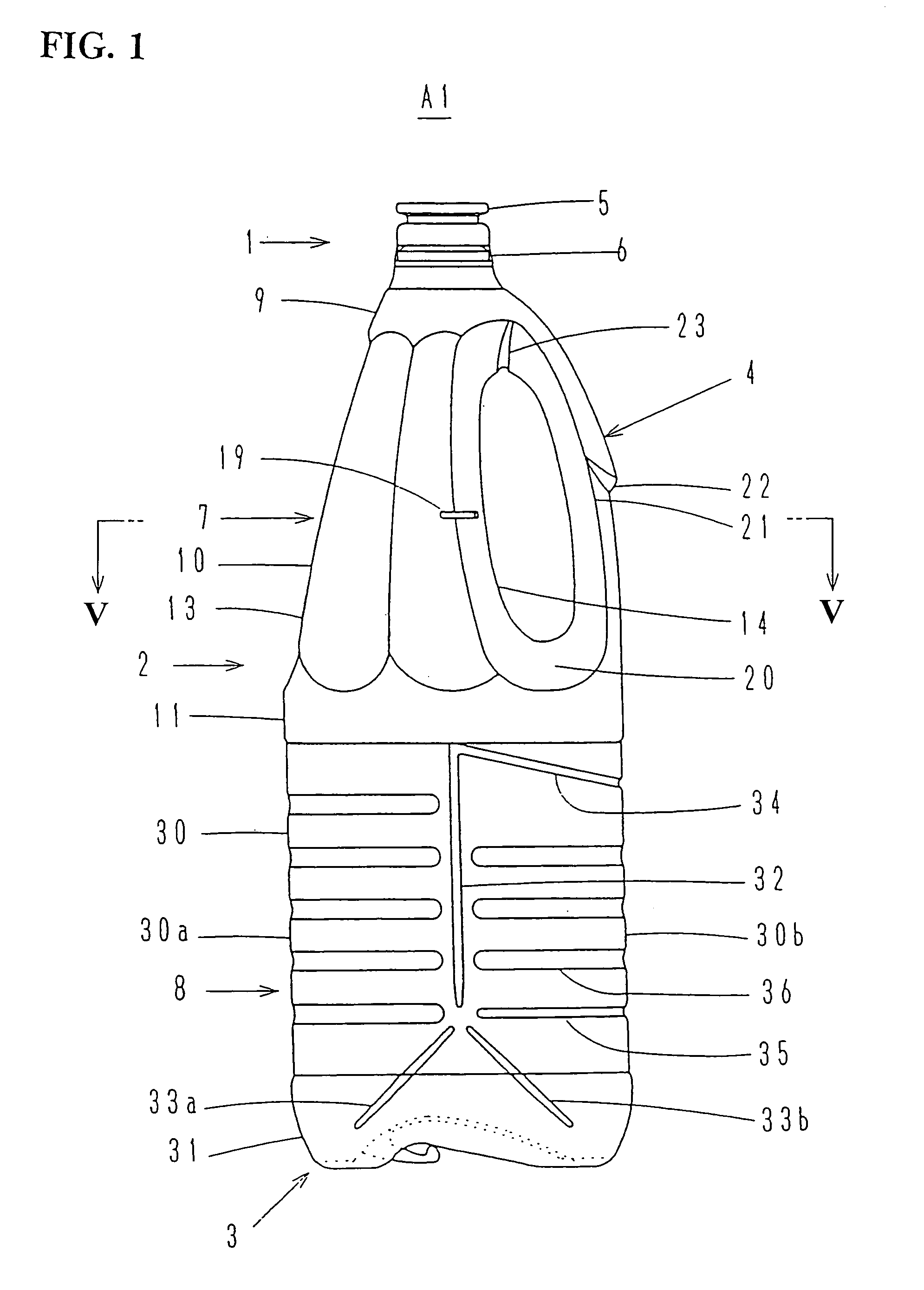
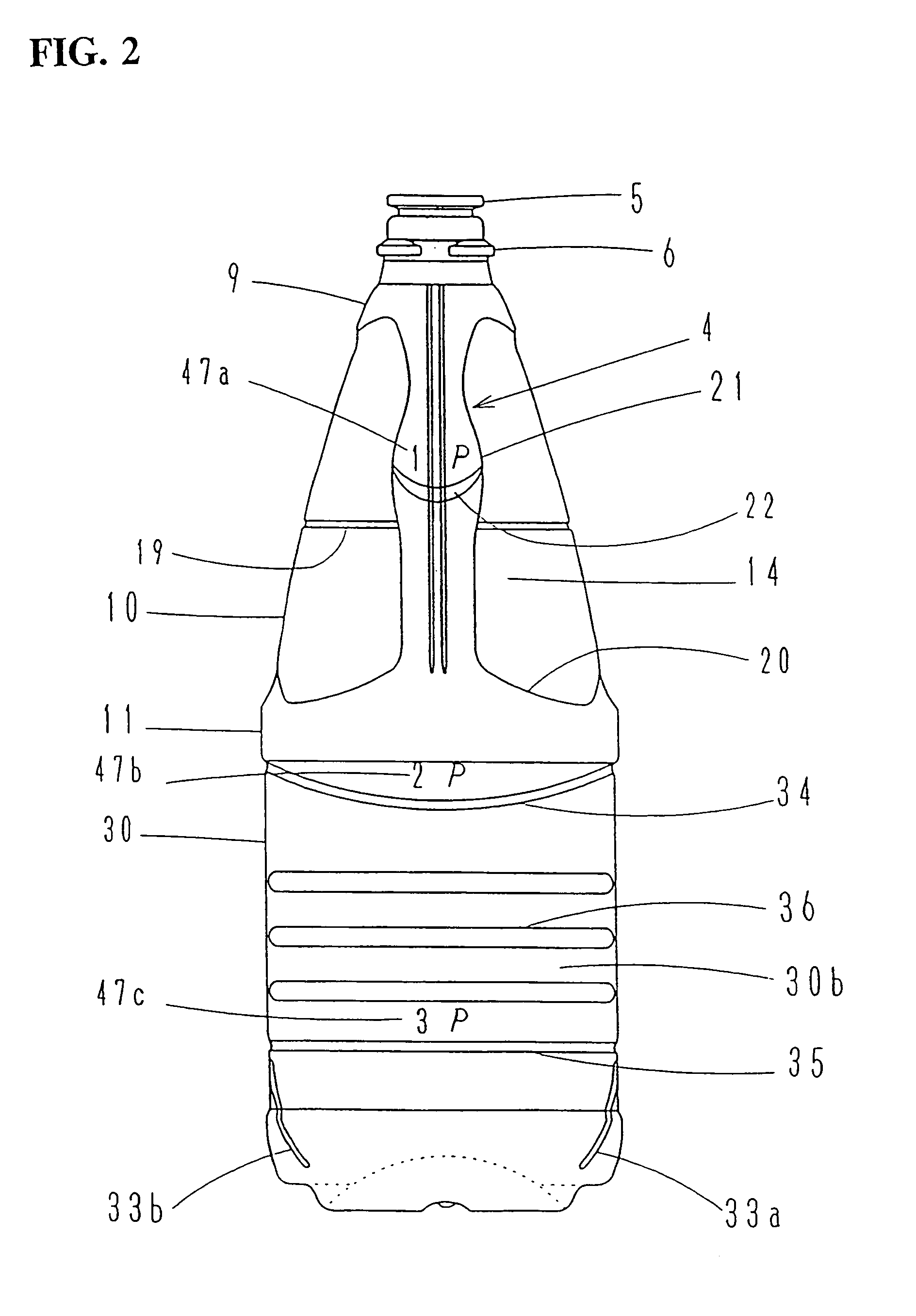
[0013]The bending deformation portion is formed in the handle of the plastic bottle to squeeze the handle and to efficiently decrease a volume of the upper body portion.
[0017]The body of the plastic bottle comprises the upper body including the handle, the lower body and the bottom. The upper body comprises the curved wall on the side surface for attaching the handle and the side wall. The bending rib extending laterally may be formed in the curved wall and the side wall adjacent to the curved wall, thereby the upper body of the bottle can be further squeezed by bending the handle.
[0018]To obtain the further folded bottle for disposal that the volume is efficiently decrease, further one or more hanging pieces may be projected from the bottom and the engaging piece having the hook may be erected from the upper end portion of the handle.

Problems solved by technology

Recently a disposing of wasted plastic has been a serious problem and a recycle of used plastic containers has been practiced.
However for keeping a certain appearance with containing and protecting liquid contents therein, plastic containers need to have a certain intensity, and a considerable squeezing force has been required for decreasing a volume of used empty plastic containers.
Especially for the plastic bottle with a handle, there has been a problem of a difficulty to squeeze the bottle due to a thick body wall thereof, and the handle portion is difficult to be squeezed.
Further together with the handle, the lower wall surface portion of the bottle body beneath the handle cannot be sufficiently deformed to efficiently decrease a volume of said upper body.
Resultantly the bulk of wasted plastic have been increased and a problem of inefficiency for transporting waste has not been solved.
While if the bottle could be easily squeezed, to prevent the bottle from recovering to the original shape, the internal pressure in the bottle should be kept its depression by putting a cap on the bottle during it being squeezed, therefore it has caused a problem of blending different kinds of materials with waste plastics at the time of recycling operation thereof.

Method used


Image

  • Plastic bottle with handle
  • Plastic bottle with handle
  • Plastic bottle with handle

Examples


second embodiment

[0136]The second embodiment will be described with reference to FIGS. 15 to 25. In the second embodiment, respective shape of the handle and the body, especially an arrangement of a bending and deformed portion of the handle and the bending rib of the body are altered.

[0137]As shown in FIGS. 15 and 16, in the second embodiment, a bottle A2 comprises a neck 50, a body 51 and a bottom 52, and the body 51 includes a handle 53.

[0138]The bottle A2 is formed by blow molding polyolefins resin and other synthetic resins for example, and may be molded from a single layer synthetic resin or from multi-layered one.

[0139]A bulged collar or ring 54 and a holding protruded lip 55 are provided around an outer circumference of the neck 50.

[0140]The body 51 comprises an upper body 56 with the handle 53 and a lower body 57 having a circular cross sectional shape. The upper body 56 comprises a semi-spherical shoulder wall 58 connected to the neck 50, a circumferential wall 59 with a ridge-line adjacen...

third embodiment

The Third Embodiment

[0181]The third embodiment in accordance with FIGS. 26 to 36 will be described herein. In this embodiment, the shape of the lower body and the arrangement of bending ribs are respectively altered.

[0182]As shown in FIGS. 26 and 27, a bottle A3 comprises a neck 101, a body 102 and a bottom 103, and the body 102 includes a handle 104.

[0183]The bottle A3 is formed by a blow molding of synthetic resins such as polyolefins and the like. The bottle A3 may be formed from a single layer of synthetic resin or from a multi-layered one.

[0184]A bulged collar or ring 105 and a protruded lip 106 are provided on an external circumference of the neck 101.

[0185]The body comprises an upper body 107 including the handle 104 and a lower body 108 having a rectangular cross sectional shape. Each of the upper body 107 and the lower body 108 has an equilateral octagonal cross section and includes eight surfaces.

[0186]The upper body 107 comprises a semi-spherical shoulder wall 109 connect...

examples

[0238]Modified examples in respect of the squeezable deformed portion of the handle, the engaging member for the neck and the bottom of the folded bottle will be described.

[0239]In the first embodiment, the squeezable deformed portion of the handle comprises stepped walls provided on the surface of the middle bulged portion of the longitudinal middle portion (that is, the bending portion), and the downward rib provided along the connecting part of the body and the curved wall (that is, bending ribs). In the second and the third embodiments, said portion comprises bending portions comprising stepped walls and concave portions vertically formed on the surface of the middle bulged portion of the handle. However, other various modified examples may be applicable.

[0240]In respect of the engaging member of the neck and the bottom of the bottle, in the second and the third embodiments, for obtaining the folded bottle by providing the engaging piece on the upper end portion and providing th...


PUM


Abstract

A squeezable plastic bottle with a handle which is bendable by forming a bending deformation portion in the handle. The bending deformation portion of the handle can be a bending portion formed in the middle portion of the longitudinal direction of the handle. Further a bending rib can be formed between the handle and the body wall surface. The body may be squeezable and deformable by forming a bending rib in the bottle body.

Description

FIELD OF THE INVENTION[0001]The present invention relates to an easily squeezable plastic bottle with a handle.BACKGROUND OF THE INVENTION[0002]Recently a disposing of wasted plastic has been a serious problem and a recycle of used plastic containers has been practiced.[0003]Further it has been encouraged and practiced to squeeze containers for disposal to decrease a volume of waste.[0004]Therefore some kinds of easily squeezable plastic containers have been proposed up to now.[0005]However for keeping a certain appearance with containing and protecting liquid contents therein, plastic containers need to have a certain intensity, and a considerable squeezing force has been required for decreasing a volume of used empty plastic containers.[0006]Especially for the plastic bottle with a handle, there has been a problem of a difficulty to squeeze the bottle due to a thick body wall thereof, and the handle portion is difficult to be squeezed.[0007]Further together with the handle, the lo...

Claims


Application Information

Patent Timeline
IPC IPC(8): B65D23/10B65D90/02B65D25/28B65D1/02B65D21/08B65D1/32B65D1/40B65D47/08B65D51/24
CPCB65D1/0292B65D1/32B65D23/10B65D23/102B65D23/106Y10S215/90B65D7/04
Inventor SHIMADA, SHINJINOSE, KAZUAKIOTA, ATSUSHIMIYAIRI, KEISUKE
Owner YOSHINO KOGYOSHO CO LTD
Learn More