Automatic transmission fluid filtration system

a technology of automatic transmission and fluid filtration, which is applied in the direction of filtration separation, lubricant mounting/connection, separation process, etc., can solve problems such as malfunctioning clutches, and achieve the effect of ensuring its volumetric efficiency

Inactive Publication Date: 2008-04-15
SONNAX INDS
View PDF3 Cites 13 Cited by
  • Summary
  • Abstract
  • Description
  • Claims
  • Application Information

AI Technical Summary

Problems solved by technology

If the pump intake is exposed and air is permitted to enter the pump, line pressure may drop enough to cause the clutches to malfunction.
This is a particular problem during cold start-up, hot idle, and high volume / demand situations.

Method used


Image

  • Automatic transmission fluid filtration system
  • Automatic transmission fluid filtration system
  • Automatic transmission fluid filtration system

Examples


Embodiment Construction

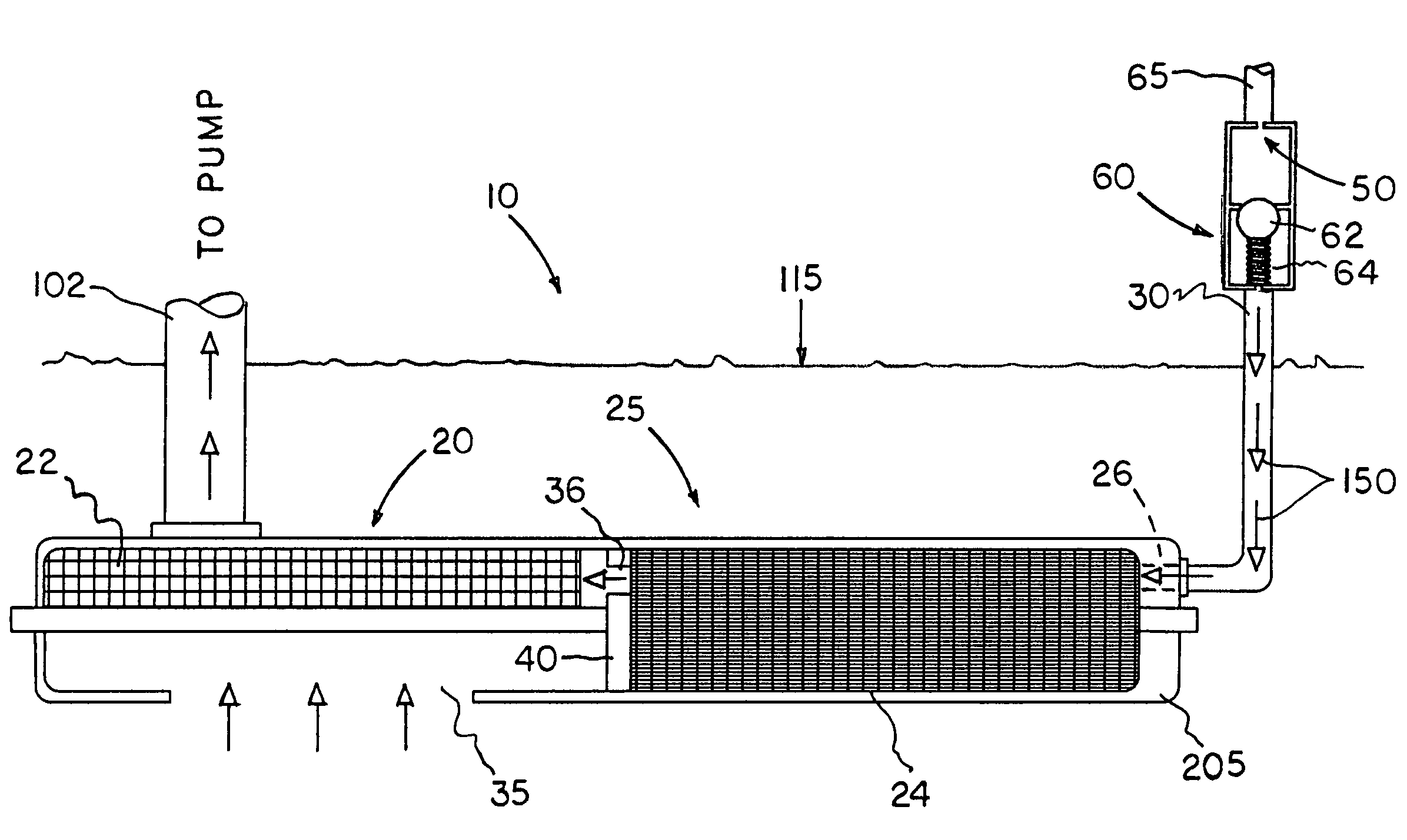
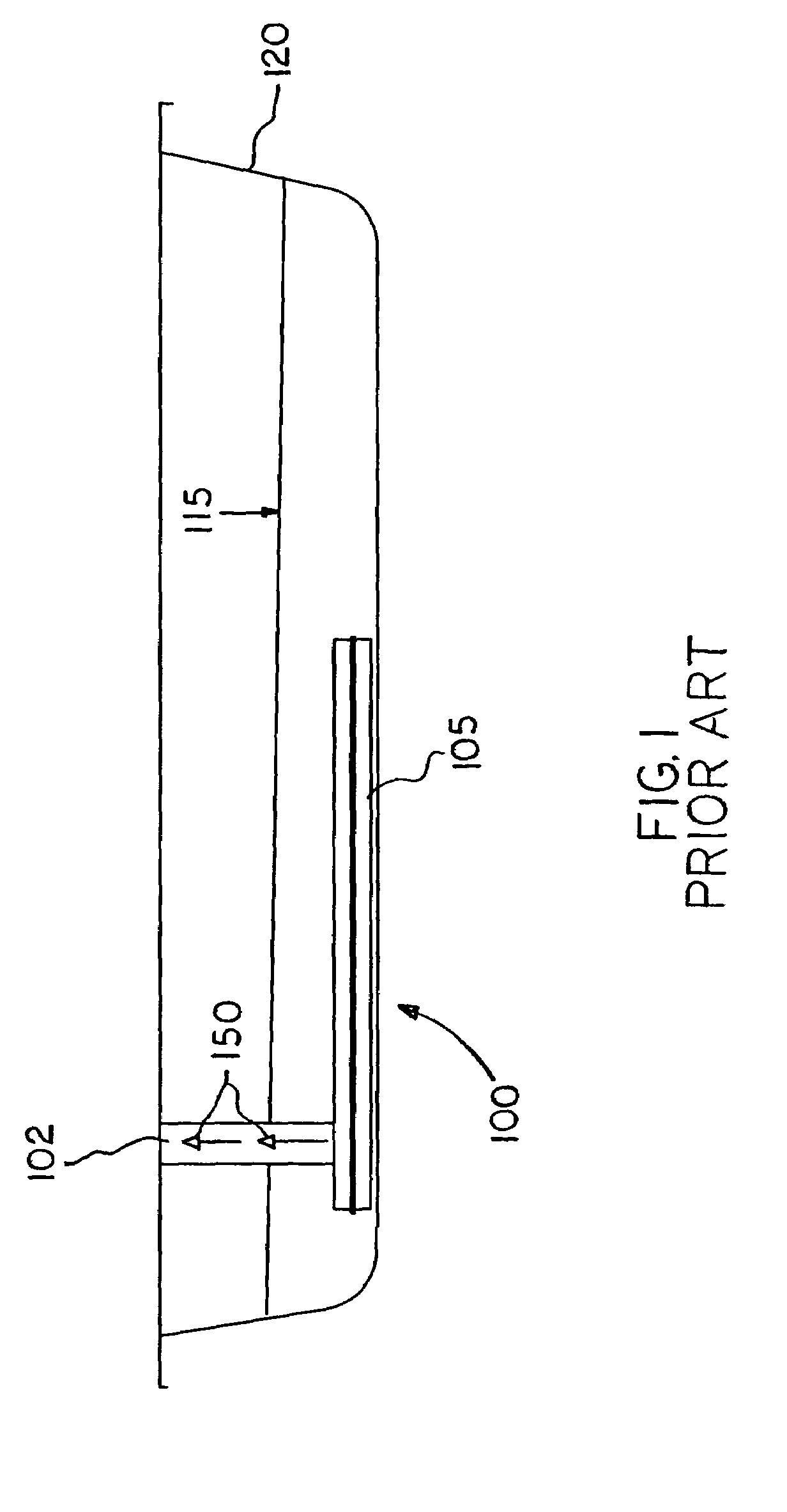
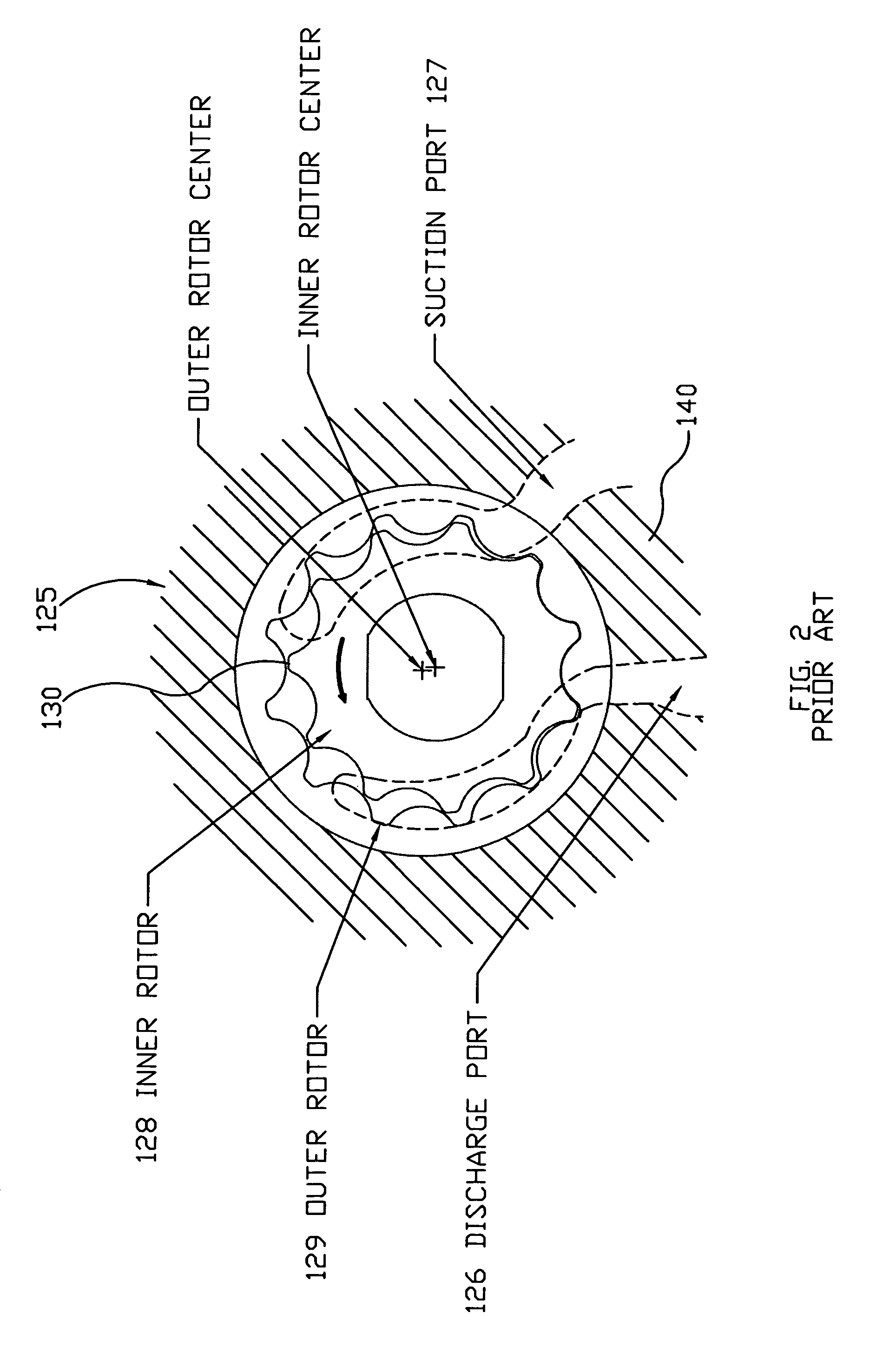
[0017]Prior to describing the present invention in detail, it may be beneficial to briefly discuss the structure and function of a conventional ATF filter in an automatic transmission. With further reference to the drawings there is shown an illustration of such a conventional ATF filter, indicated generally at 100, within the sump of an automatic transmission. The ATF filter 100 is comprised of a housing 105, which is submerged below the ATF level as at 115 in the pan 120. Housing 105 is disposed in fluid communication via suction tube 102 with the transmission pump, indicated generally at 125 and shown in FIG. 2, attached to the transmission case (not shown).

[0018]A positive displacement pump 125 of the Gerotor type is shown in FIG. 2 for purposes of explanation. Of course, other types of positive displacement pumps such as gear pumps and vane pumps may be utilized with the present invention. In the Gerotor type pump 125 as the inner rotor 128 turns each of its teeth maintains con...


PUM

PropertyMeasurementUnit
diametersaaaaaaaaaa
pressureaaaaaaaaaa
pressureaaaaaaaaaa

Abstract

An automatic transmission fluid (ATF) filtration system that combines both coarse filtering mesh and microfine depth filtering elements simultaneously to remove a wide range of particulate matter, but also maintains an unrestricted flow of ATF to the pump to ensure its volumetric efficiency is disclosed. In the present invention ATF at system pressure is delivered via a hydraulic circuit to a microfine depth filtering element for depth filtration (i.e. several layers of filter media) and, thereafter, is passed into the intake of the coarse filter element or, alternatively, between the intake of the coarse filter element and the pump intake. Because ATF flow through the coarse filter element is continuous and independent of the microfine depth filter element, the volumetric efficiency of the pump is maintained in all phases of operation even at the highest demand points such as at cold start-up, hot idle, and high volume / demand situations.

Description

CROSS-REFERENCE TO RELATED APPLICATIONS[0001]This application claims the benefit under 35 U.S.C. 119(e) of U.S. Provisional Patent Application No. 60 / 508,596 filed Oct. 3, 2003 entitled Automatic Transmission Fluid Filtration System.BACKGROUND OF INVENTION[0002]The present invention relates to automatic transmissions for land vehicles and, more particularly, to an automatic transmission fluid filtration system for such automatic transmissions.[0003]Maintaining automatic transmission fluid (hereinafter “ATF”) in a clean condition free of particulates and contamination is critical to the proper function of an automatic transmission. Most automatic transmissions and transaxles use a standard wet sump system where the ATF drains by gravity into the pan and the pump takes it up directly and discharges it to the hydraulic system. In a typical automotive application an ATF filter is submerged in the pan in fluid communication with the transmission pump. As the pump rotates ATF is drawn fro...

Claims


Application Information

Patent Timeline
Patent Type & Authority Patents(United States)
IPC IPC(8): B01D35/027B01D35/02F01M1/10F01M11/03F16N39/06
CPCB01D35/0273F16H61/00
Inventor NADER, GREGG A.
Owner SONNAX INDS
Why Eureka
Try Eureka