Reflection-type liquid crystal display device

a liquid crystal display and reflection-type technology, applied in the field of reflection-type liquid crystal display devices, can solve the problems of air bubbles infiltration, poor display quality, and difficulty in using this constitution except the small devices, and achieve the effect of suppressing the blurring of images and suppressing the decrease of contras

Inactive Publication Date: 2008-04-15
SHARP KK
View PDF18 Cites 51 Cited by
  • Summary
  • Abstract
  • Description
  • Claims
  • Application Information

AI Technical Summary

Benefits of technology

[0030]It is therefore an object of this invention to suppress a decrease in the contrast caused by the reflection by the interfaces to the air layer without decreasing the quality of display.

Problems solved by technology

The low contrast narrows the range of reproducing colors, and the quality of display is very poor.
However, when the light guide plate 93 and the liquid crystal display panel 80 having different coefficients of thermal expansion are stuck together, there occurs peeling due to thermal shock.
Or, when the rigid bodies are stuck together, air bubbles tend to infiltrate.
Therefore, the use of this constitution involves difficulty except the small devices.
However, the above constitution of FIG. 18B is accompanied by a problem of conspicuous interference rainbow due to moiré fringes between the prism 94 of the light guide plate 93 and the pixels of the liquid crystal display panel 80, and due to interference between the reflection structure of the liquid crystal display panel 80 and the pixels.
There further exists a problem in that the circularly polarizing plate 100 and the liquid crystal display panel 80 are abraded by the external pressure of input using a pen, and the circularly polarizing plate 100 is scarred.

Method used


Image

  • Reflection-type liquid crystal display device
  • Reflection-type liquid crystal display device
  • Reflection-type liquid crystal display device

Examples


first embodiment

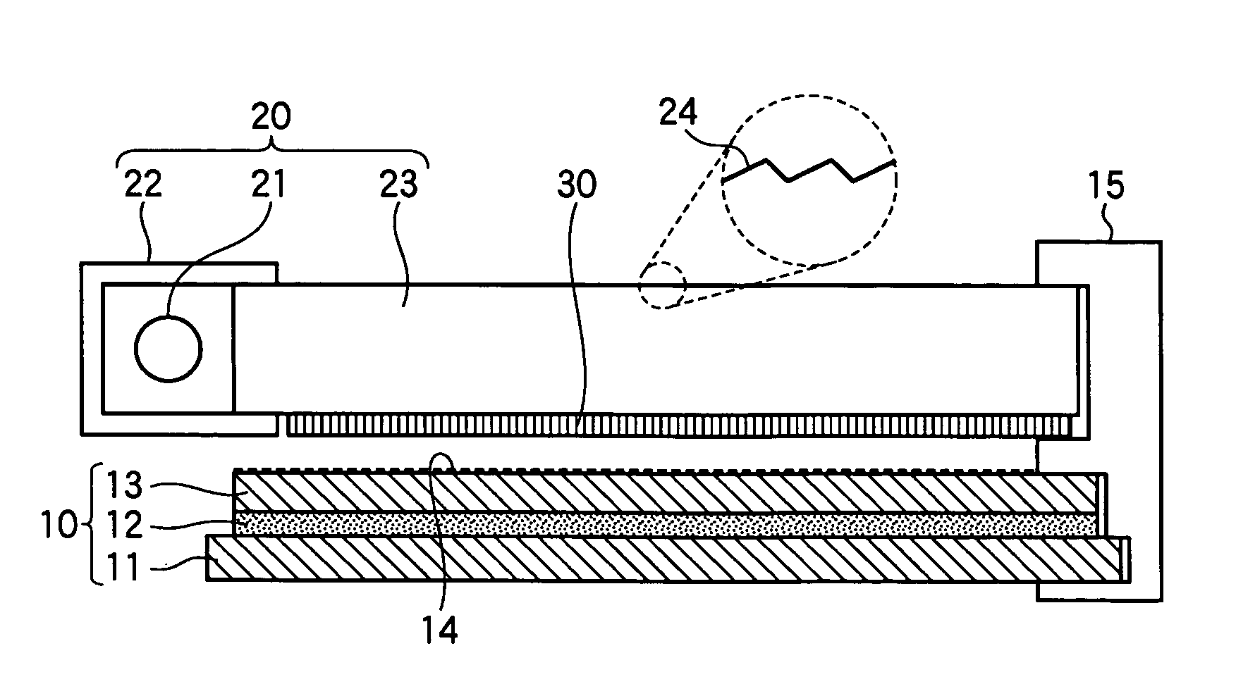
[0128]A reflection-type liquid crystal display device according to the invention will now be described with reference to FIG. 2.

[0129]FIG. 2 is a sectional view schematically illustrating the reflection-type liquid crystal display device according to the first embodiment of the present invention, which comprises a front light unit 20, and a liquid crystal display panel 10 constituted by a liquid crystal layer 12 held between a TFT substrate 11 having an alignment film provided on a glass substrate via a reflection electrode and a CF substrate 13 having an alignment film provided on a glass substrate via a transparent electrode. The front light unit 20 and the liquid crystal display panel 10 are firmly held by a frame 15 being opposed to each other maintaining a small gap of not larger than, for example, 1 mm.

[0130]The front light unit 20 includes a source 21 of light constituted by a cold cathode tube containing Ar or Ne gas and a trace amount of Hg, a reflector 22 for reflecting an...

second embodiment

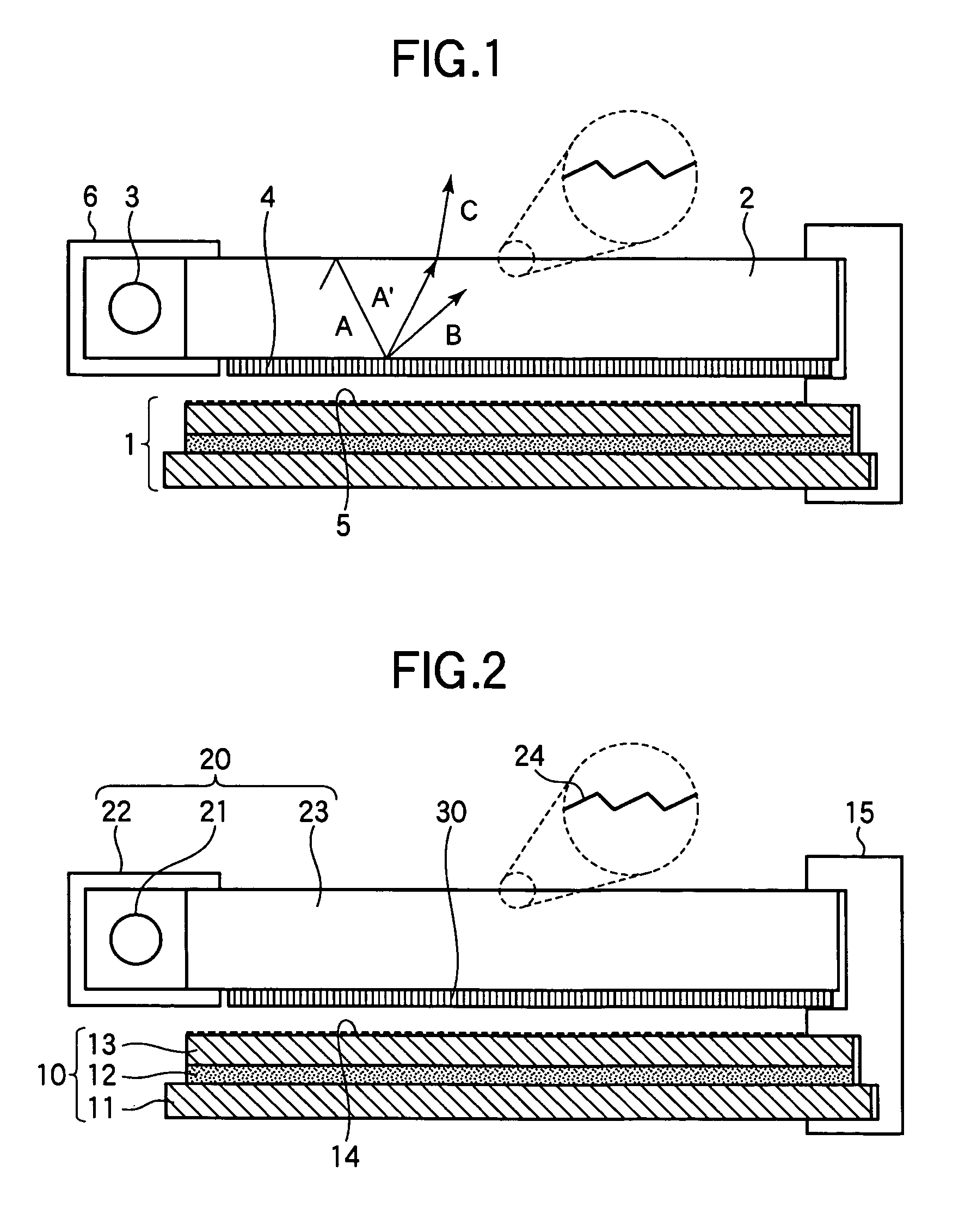
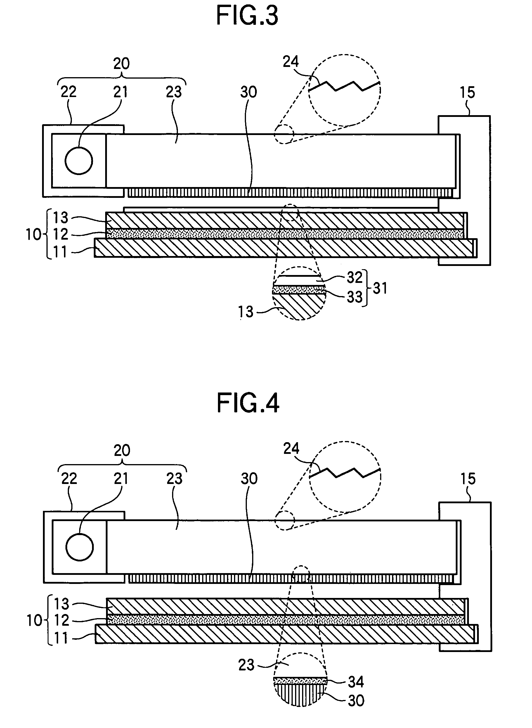
[0137]Next, the reflection-type liquid crystal display device according to the present invention will be described with reference to FIG. 3.

[0138]FIG. 3 is a sectional view schematically illustrating the reflection-type liquid crystal display device according to the second embodiment of the invention. The basic constitution is the same as that of the reflection-type liquid crystal display device of the above first embodiment. In the second embodiment, however, the surface of the liquid crystal display panel 10 is not roughened as designated at rough surface 14 but is, instead, provided with a light-diffusing film 31 which comprises a TAC film 32 and a sticking layer 33 containing a light-diffusing material.

[0139]The light-diffusing material, in this case, may be, for example, TiOx and its amount can be determined to maintain a balance in the effects for decreasing the blurring amount of image, moiré fringes and interference rainbow, and may be such that H≦50[%].

[0140]In this case, t...

third embodiment

[0141]Next, the reflection-type liquid crystal display device according to the present invention will be described with reference to FIG. 4.

[0142]FIG. 4 is a sectional view schematically illustrating the reflection-type liquid crystal display device according to the third embodiment of the invention. The basic constitution is the same as that of the reflection-type liquid crystal display device of the above first embodiment. In the third embodiment, however, the surface of the liquid crystal display panel 10 is not roughened as designated at rough surface 14 and, besides, the polarizing element 30 is stuck to the light guide plate 23 by using a sticking layer 34 containing a light-diffusing material.

[0143]In the third embodiment, the light directed by the prism 24 toward the side of the liquid crystal display panel is diffused by the sticking layer 34 containing the light-diffusing material provided on the back surface of the light guide plate 23, and is converted in a direction in ...


PUM

PropertyMeasurementUnit
hazeaaaaaaaaaa
wavelengthsaaaaaaaaaa

Abstract

To suppress a decrease in the contrast caused by the reflection on the interface to the air layer without decreasing the quality of display. A reflection-type liquid crystal display device includes a light guide plate having a polarizing element stuck or adhered thereto on the side facing a reflection-type liquid crystal display panel, a source of light arranged on an end surface side of the light guide plate, and the reflection-type liquid crystal display panel arranged maintaining a predetermined gap relative to the light guide plate, wherein a light-diffusing function is imparted to the surface of the reflection-type liquid crystal display panel on the side facing the light guide plate.

Description

BACKGROUND OF THE INVENTION[0001]1. Field of the Invention[0002]This invention relates to a reflection-type liquid crystal display device and, particularly, to a reflection-type liquid crystal display device used for low-power-consumption units such as portable terminals and having a feature in the constitution for suppressing a decrease in the contrast caused by the reflection on the interface without decreasing the quality of display.[0003]2. Description of the Related Art[0004]Owing to their features such as small in size, light in weight and low power consumption, the liquid crystal display devices have been widely used as data equipment terminals, TVs, portable data equipment terminals, display monitors such as video cameras, etc.[0005]The liquid crystal material does not emit the light by itself and a source of light is necessary when it is used as a display device. In the case of a reflection-type liquid crystal display device used as a low-power-consumption unit such as a po...

Claims


Application Information

Patent Timeline
Patent Type & Authority Patents(United States)
IPC IPC(8): G02F1/1335G02B6/00G02F1/13357G02F1/13363
CPCG02B6/0051G02B6/0056G02F1/133504G02F1/133528G02F1/13362G02F1/133615G02F2001/133616G02F1/13363G02F2001/133541G02F1/133541G02F1/133616G02F1/1335
Inventor HAMADA, TETSUYATASHIRO, KUNIHIROSUGAWARA, MARISUZUKI, TOSHIHIRO
Owner SHARP KK
Why Eureka
Try Eureka