Lens positioning systems and methods

a technology of positioning system and lens, applied in the field of optics, can solve the problems of optical components not always available within particular desired tolerances, images appearing off center or distorted on the imager, and light not being properly focused on the imager

Active Publication Date: 2008-04-15
DIGITALPTICS MEMS
View PDF7 Cites 54 Cited by
  • Summary
  • Abstract
  • Description
  • Claims
  • Application Information

AI Technical Summary

Benefits of technology

[0012]In accordance with another embodiment of the present invention, a method of positioning a lens barrel, includes: inserting a lens barrel into a ring member having a substantially cylindrical interior surface; and exerting pressur...

Problems solved by technology

In particular, if lenses are skewed in one or more degrees of rotational freedom or translational freedom, light may not be properly focused on the imager.
This can result in images appearing off centered or distorted on the imager.
Unfortunately, optical components may not always be available within particular desired tolerances.
The accumulation of variations in optical component characteristics, dimensions, and tolerances can result in misalignment of lenses.
In addition, even when lenses are initially properly a...

Method used


Image

  • Lens positioning systems and methods
  • Lens positioning systems and methods
  • Lens positioning systems and methods

Examples


Embodiment Construction

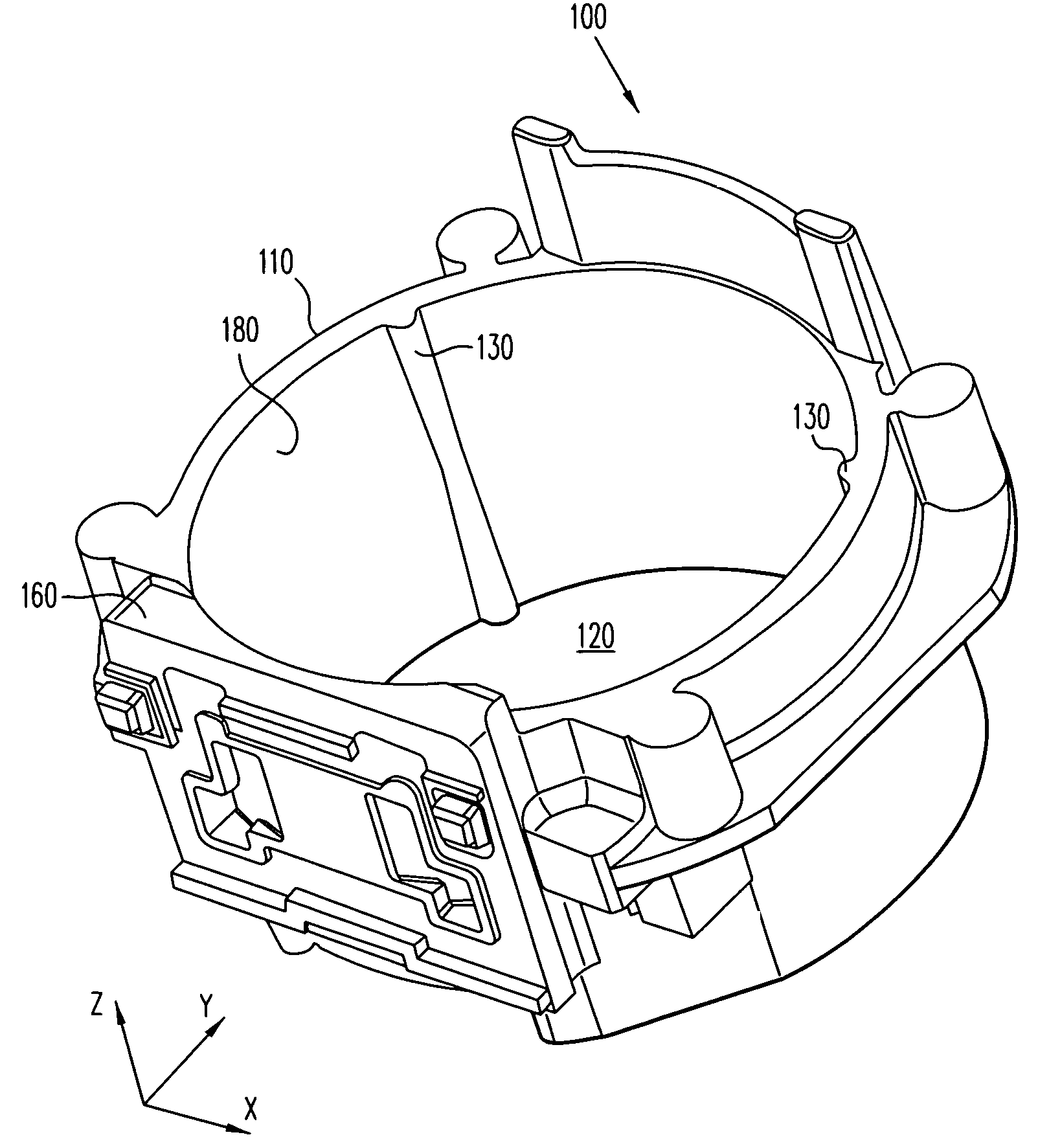
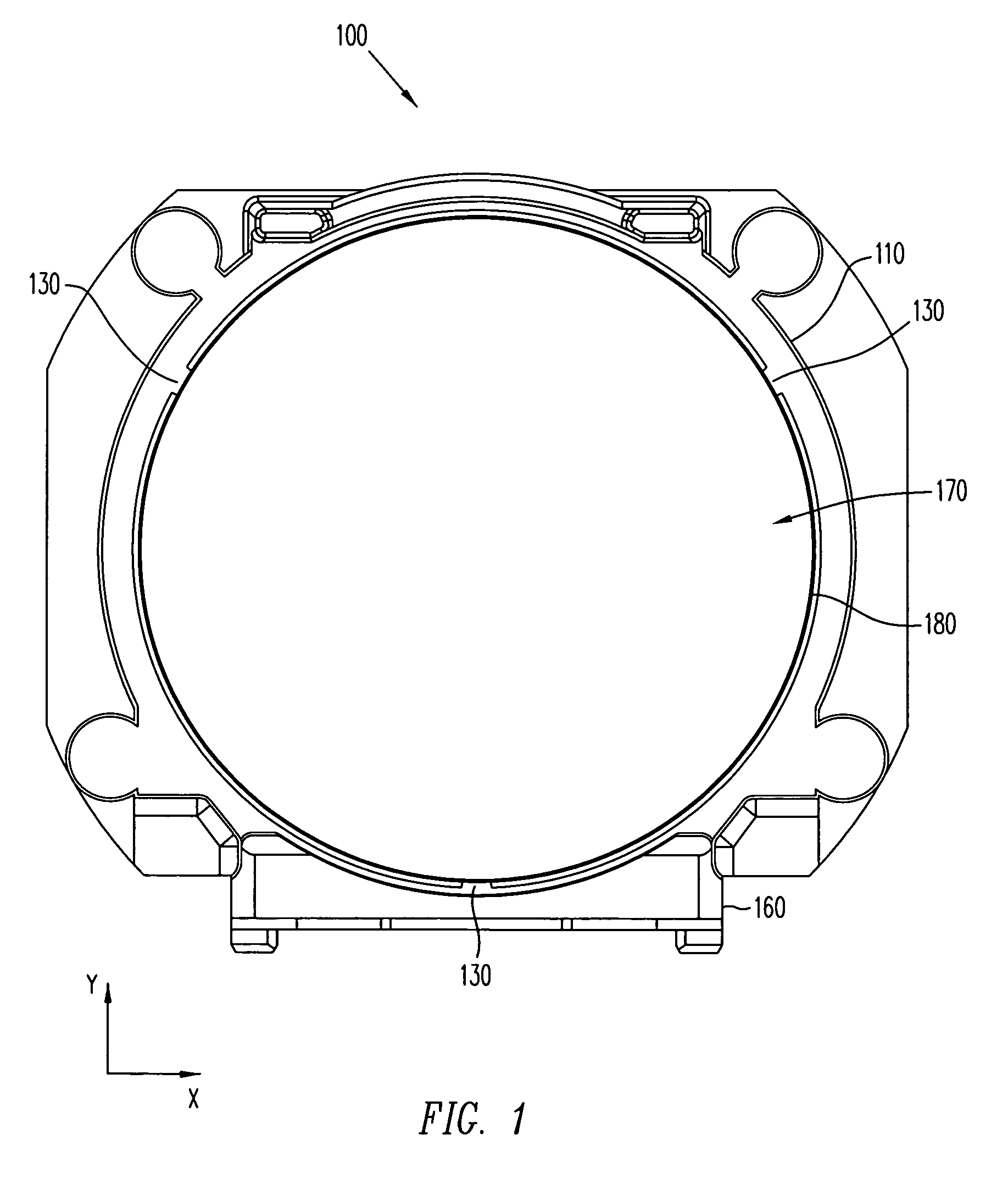
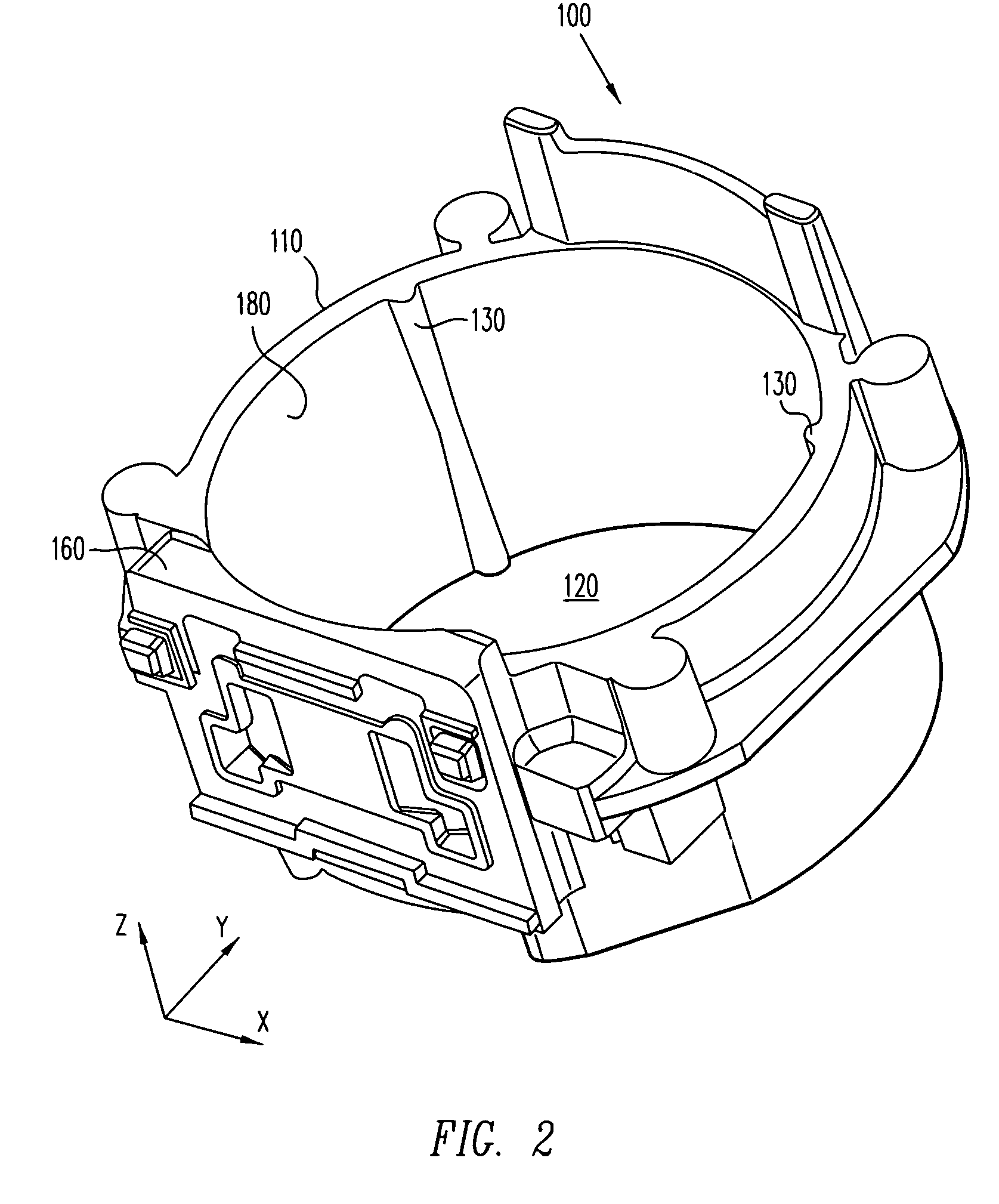
[0024]Referring now to the drawings wherein the showings are for purposes of illustrating embodiments of the present invention only, and not for purposes of limiting the same, FIGS. 1 and 2 illustrate front and perspective views, respectively, of a lens mount 100 having a plurality of ribs 130 in accordance with an embodiment of the present invention. Lens mount 100 includes a ring member 110 connected with a base member 160. A substantially cylindrical interior surface 180 of lens mount 100 defines a substantially cylindrical interior space 120. Ribs 130 are disposed on interior surface 180 and can exhibit substantially hemispherical surfaces facing toward interior space 120.

[0025]As illustrated in FIG. 1, a lens barrel 170 can be inserted into ring member 110. For example, in one embodiment, threads (not shown) can be provided on an external surface of lens barrel 170 for engaging threads (not shown) on interior surface 180. As a result, lens barrel 170 may be screwed into ring me...


PUM


Abstract

An improved lens mount and related lens and lens barrel positioning methods are provided. In one example, a lens mount for use with a miniature camera can include a ring member having a substantially cylindrical interior surface defining a substantially cylindrical interior space. A plurality of elongate ribs are disposed on the interior surface of the ring member and are adapted to exert pressure against an external surface of a lens barrel received by the ring member. In another example, a method of positioning a lens barrel includes inserting a lens barrel into a ring member having a substantially cylindrical interior surface. Pressure can be exerted against an external surface of the lens barrel from a plurality of elongate ribs disposed on the interior surface of the ring member. The pressure can prevent rotation of the lens barrel along at least three axes of rotational freedom.

Description

CROSS-REFERENCE TO RELATED APPLICATIONS[0001]This application is a continuation application of U.S. patent application Ser. No. 11 / 487,908 filed on Jul. 17, 2006 entitled “Lens Positioning Systems and Methods”, now abandoned, which is a continuation-in-part application of U.S. patent application Ser. No. 11 / 361,608 filed on Feb. 24, 2006 entitled “Autofocus Camera”, which claims the benefit of U.S. Provisional Patent Application No. 60 / 657,261 filed on Feb. 28, 2005 entitled “Autofocus Camera”, all of which are incorporated herein by reference.BACKGROUND[0002]1. Field of the Invention[0003]The present invention generally relates to optics and, more particularly, to the alignment of lenses that are suitable for use with miniature cameras.[0004]2. Related Art[0005]Digital cameras typically use one or more lenses to provide focused or zoomed images to an imager. In order for the imager to obtain accurate images, it is important that the lenses be properly aligned with the imager. In pa...

Claims


Application Information

Patent Timeline
IPC IPC(8): G02B7/02G02B21/00G02B7/04G03B17/00G02B23/00
CPCG03B7/083G02B7/02G03B17/12G03B2205/0007
Inventor GUTIERREZ, ROMAN C.CALVET, ROBERT J.
Owner DIGITALPTICS MEMS
Why Eureka
Try Eureka