Storage subsystem

a storage subsystem and subsystem technology, applied in the field of storage subsystems, can solve the problems of inadequate installation method of hdd while retaining the conventional storage device installation method, and achieve the effects of improving stability or reliability, simplifying maintenance-related manipulation and raising the cooling efficiency of the storage subsystem

Inactive Publication Date: 2008-04-15
HITACHI LTD
View PDF15 Cites 79 Cited by
  • Summary
  • Abstract
  • Description
  • Claims
  • Application Information

AI Technical Summary

Benefits of technology

[0005]Therefore, an object of the present invention is to provide a method of mounting storage devices that serves at least one of the miniaturization of the storage subsystem, an increased capacity, and a higher performance.
[0007]A further object of the present invention is to raise the cooling efficiency of the storage subsystem.
[0008]Another object of the present invention is to simplify maintenance-related manipulation of the storage subsystem and to increase stability or reliability.
[0018]In a sixth embodiment, the storage subsystem further comprises a cooling portion that causes a gas for cooling the storage devices arranged on the storage device arrangement portion to flow to the storage device arrangement portion; and a storage device dummy that is disposed on the storage device arrangement portion so that the flow of gas is not disturbed when the maximum number of storage devices that can be arranged is not arranged on the storage device arrangement portion.

Problems solved by technology

However, simply changing the installed storage device to an SFF-HDD while retaining the conventional storage-device installation method is considered inadequate from at least one perspective among a variety of perspectives such as high-density mounting of the storage device, more efficient cooling of the storage subsystem and maintenance of the storage subsystem, for example.

Method used


Image

  • Storage subsystem
  • Storage subsystem
  • Storage subsystem

Examples


first embodiment example

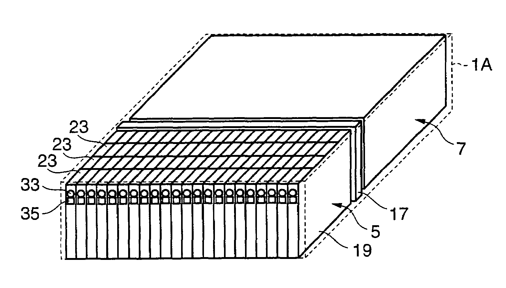
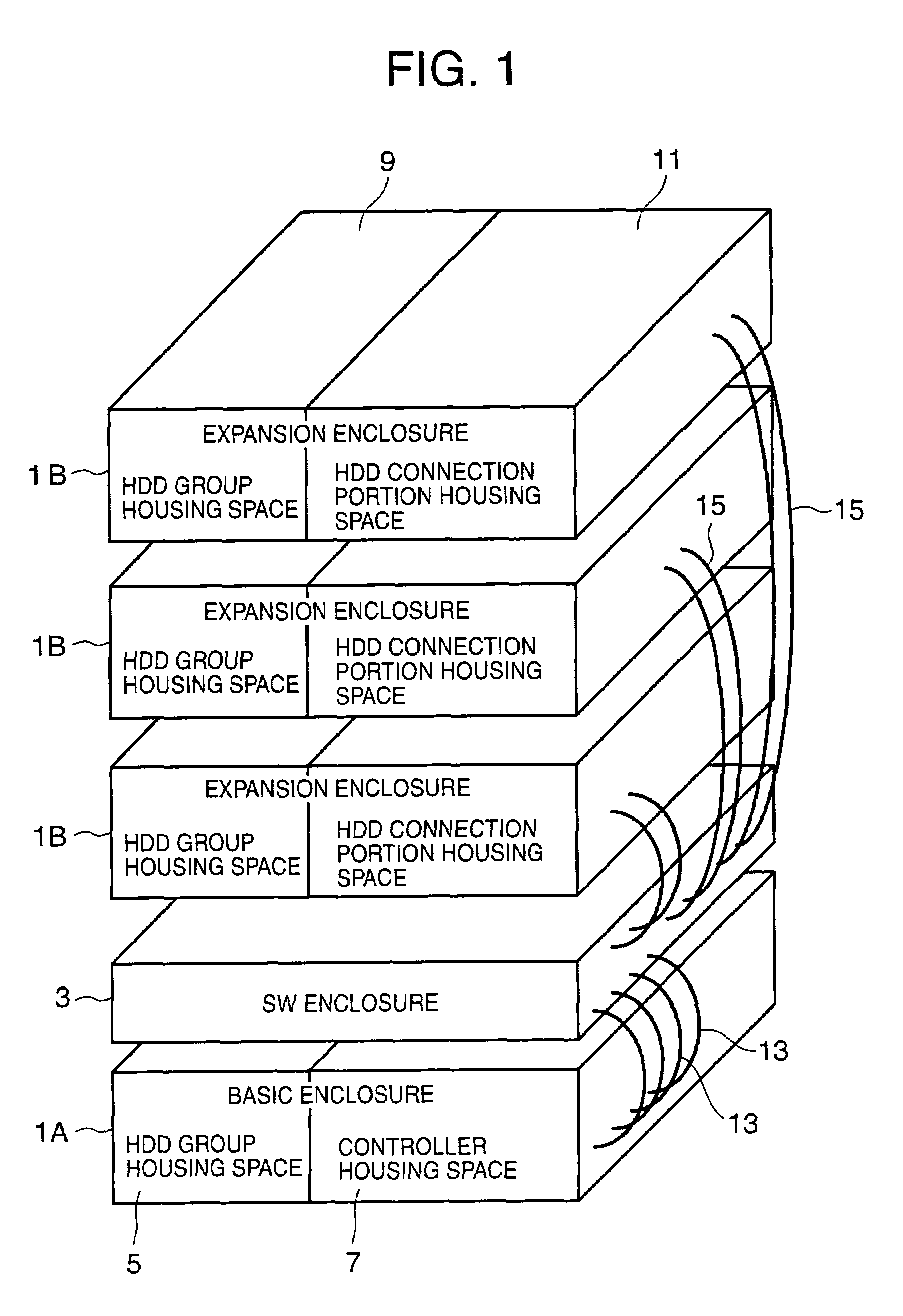
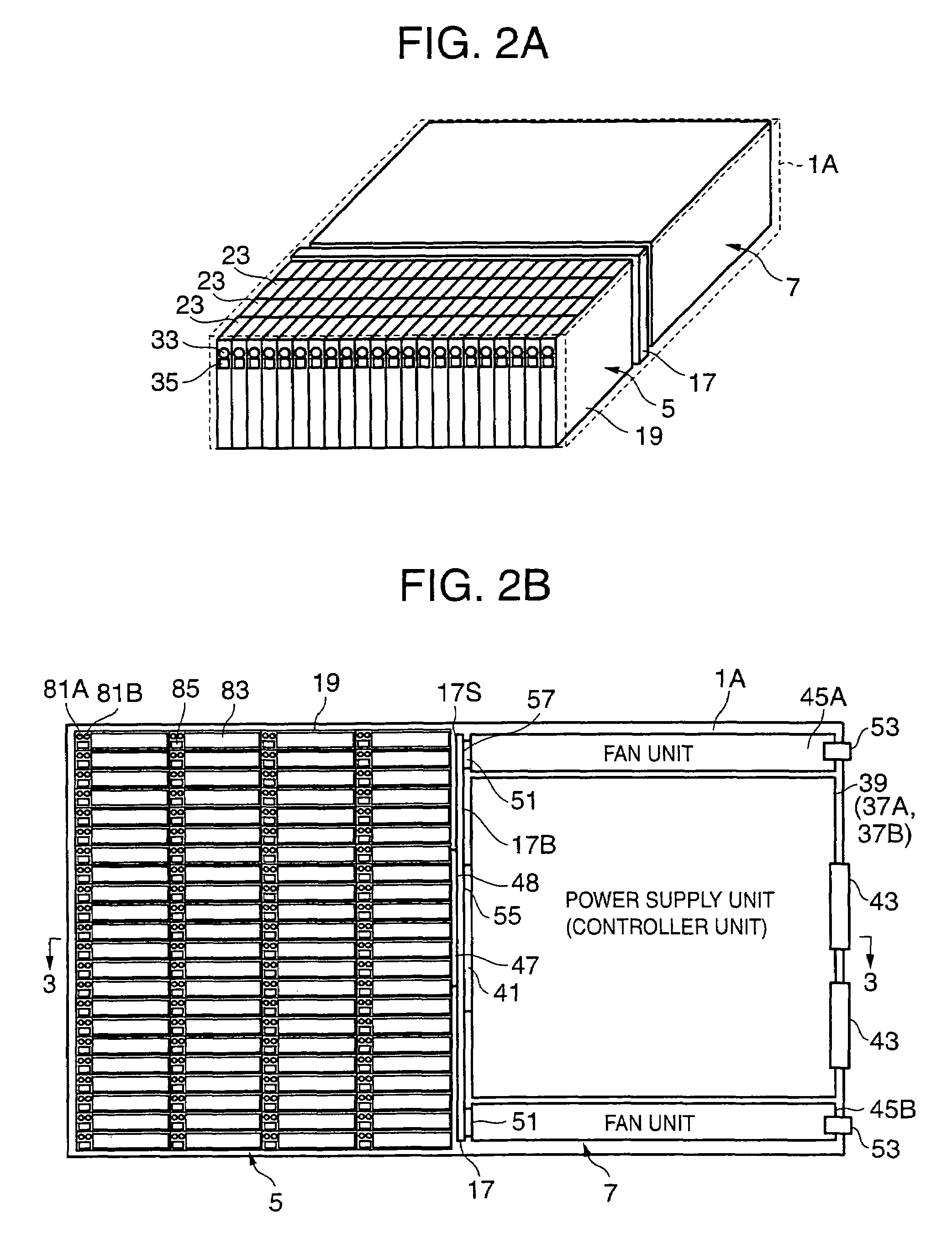
[0056]FIG. 1 provides a schematic external view of a storage subsystem according to a first embodiment example of an embodiment of the present invention.

[0057]A storage subsystem 1 is a RAID (Redundant Array of Inexpensive Disks) system, for example. The storage subsystem 1 comprises a basic enclosure 1A, a plurality of (or a single) expansion enclosures 1B, 1B, . . . , and a switch enclosure (abbreviated to ‘SW enclosure’ hereinafter) 3 that electrically connects the basic enclosure 1A and expansion enclosures 1B.

[0058]The SW enclosure 3 comprises a switch device (not shown). An HDD connection portion (not shown) within the expansion enclosure 1B, which will be described subsequently, is connected to the switch device via a cable 15. Further, controller units (not shown) in the basic enclosure 1A (described subsequently) are connected to the switch device via cables 13. As a result, the controller units are able to access the HDDs in the expansion enclosure 1B via the switch device...

second embodiment example

[0132]In the second embodiment, the method of withdrawing the HDD group installation drawer 19 differs from that of the first embodiment example.

[0133]Withdrawal methods include, for example, a method (referred to as the ‘integrated withdrawal method’ hereinafter) in which the HDD group installation drawer 19 is withdrawn integrally with the rear-side parts (the back plane 17 and the parts that exist further in the depth direction than the back plane 17) and a method (referred to as the ‘separate withdrawal method’ hereinafter) in which the HDD group installation drawer 19 is withdrawn separately from the back plane 17. Variations on each withdrawal method will be described below.

[0134](A) Integrated Withdrawal Method

[0135]FIG. 12A shows a first variation on the integrated withdrawal method.

[0136]According to the first variation, a cable (hereinafter ‘external cable’) 77, which is connected to the rear-side connector 43 of the power supply unit 39, controller units 37A, 37B, and so ...

third embodiment example

[0150]In the third embodiment example, the removal method for the HDD 23 differs from that of the first embodiment example.

[0151]FIG. 14A shows a first variation on the removal method for the HDD 23.

[0152]In the first variation, an elastic body (a spring, for example) 511 whose height runs vertically is provided between the HDD mounting portion 31 and HDD group mounting substrate 21. In this first variation, the mounting and removal of the HDD 23 is executed according to the following processing flow.

[0153]That is, the HDD 23 is pressed vertically downward for insertion into the HDD slot 83 and, when the HDD 23 no longer extends after the elastic body 511 has collapsed according to a certain measure, the elastic body 511 returns to and stops in a position below the original height thereof such that the upper face 23U of the HDD 23 is then located in the same position as the face of the HDD slot 83 or in a position below same. The HDD 23 thus enters a mounted state.

[0154]Thereafter, ...


PUM


Abstract

The storage subsystem is connected to an external device and comprises a storage device arrangement portion, on which a plurality of storage devices is arranged, and a control device that controls communications between the plurality of storage devices arranged on the storage device arrangement portion and the external device. The storage device arrangement portion is constituted such that the plurality of storage devices is arranged upright in the directions of two dimensions.

Description

CROSS-REFERENCE TO PRIOR APPLICATION[0001]This application relates to and claims priority from Japanese Patent Application No. 2004-251940, filed on Aug. 31, 2004, the entire disclosure of which is incorporated herein by reference.FIELD OF THE INVENTION[0002]The present invention relates to a storage subsystem that comprises a plurality of storage devices.BACKGROUND OF THE INVENTION[0003]As a storage subsystem that comprises a plurality of storage devices, the storage subsystem disclosed by Japanese Patent Application Laid Open No. 2004-022058, for example, is known. This storage subsystem comprises a deep enclosure. Storage devices, which are inserted in the depth direction via the front side, are arranged in the enclosure. In other words, the user is able to install a storage device in the storage subsystem by inserting a storage device in the enclosure in the depth direction via the front side.SUMMARY OF THE INVENTION[0004]There is a desire for miniaturization of storage subsyste...

Claims


Application Information

Patent Timeline
Patent Type & Authority Patents(United States)
IPC IPC(8): H05K7/20H05K5/00H05K7/16
CPCG11B33/142G11B27/00
Inventor HONDA, KIYOSHISUGIMOTO, SHUJISATO, MASAHIKO
Owner HITACHI LTD
Why Eureka
Try Eureka