Fault location on a telecommunications network

a fault location and telecommunications network technology, applied in data switching networks, instruments, frequency-division multiplexes, etc., can solve problems such as short circuits between wires, and prone to faults in terminal lines, so as to mitigate errors in average values

Inactive Publication Date: 2008-04-15
BRITISH TELECOMM PLC
View PDF7 Cites 9 Cited by
  • Summary
  • Abstract
  • Description
  • Claims
  • Application Information

AI Technical Summary

Benefits of technology

[0018]Each distribution location preferably includes the total number of historical faults and the number of historical faults at the predetermined point on the network for the distribution location, allowing a simple calculation of the possibility of the new fault being at the predetermined point, for example the node location, such as the PCP.
[0019]Preferably if the probability represented by a distribution location is derived from an unrepresentative sample, the fault line parameter is further compared against probabilities represented by one or more adjacent distribution locations. Accordingly the calculation can spread along the distribution until a representative sample is achieved. The distribution preferably comprises at least one axis comprising a comparison of historical fault line parameter values and corresponding historical non-fault line parameter values, for example a first axis comprising a comparison of historical fault line parameter values and corresponding historical healthy line values, and a second axis comprising a comparison of historical fault line parameter values and a value representative of the switch to node parameter value, and / or a first axis comprising a comparison of historical fault line parameter values and corresponding healthy line parameter values, and a second axis comprising a comparison of historical fault line parameter values and the historical switch to node parameter value closest to the fault line parameter value. The offset for the switch to node parameter is thus compensated, and errors in an average value can be mitigated for that parameter.

Problems solved by technology

Terminating lines are prone to faults such as dis-connections, short circuits between the two wires of the pair of wires, and short circuits between one of the wires and earth.
Causes of such faults include ingress of water into a node and also physical damage to a node.
The procedure itself is labour intensive, and time consuming.
Also, because it is also necessary to test several nodes before the correct one is found, the problems of cost and time are exacerbated.
This system requires complex processing of data on site.
In addition, where there is more than one line running to the PCP, or cabinet, a single reference value may not be representative if there is re-routing or if a line between the switch and exchange follows an alternative route where there are multiple lines.

Method used


Image

  • Fault location on a telecommunications network
  • Fault location on a telecommunications network
  • Fault location on a telecommunications network

Examples


Embodiment Construction

[0038]The fault location system and method of the present invention comprises two basic operations. The system provides an arrangement capable of finding the likely location of a fault in a telecommunications system effectively by comparing a test measurement on a line with a reference value and deriving from that comparison the likely location of the fault. Accordingly, the two operations are respectively obtaining one or more reference values to form the basis of the comparison, and carrying out the comparison itself.

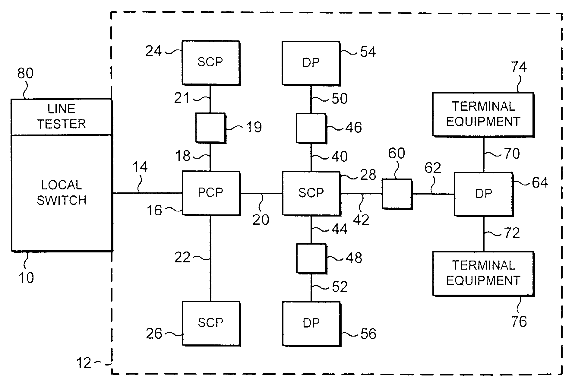
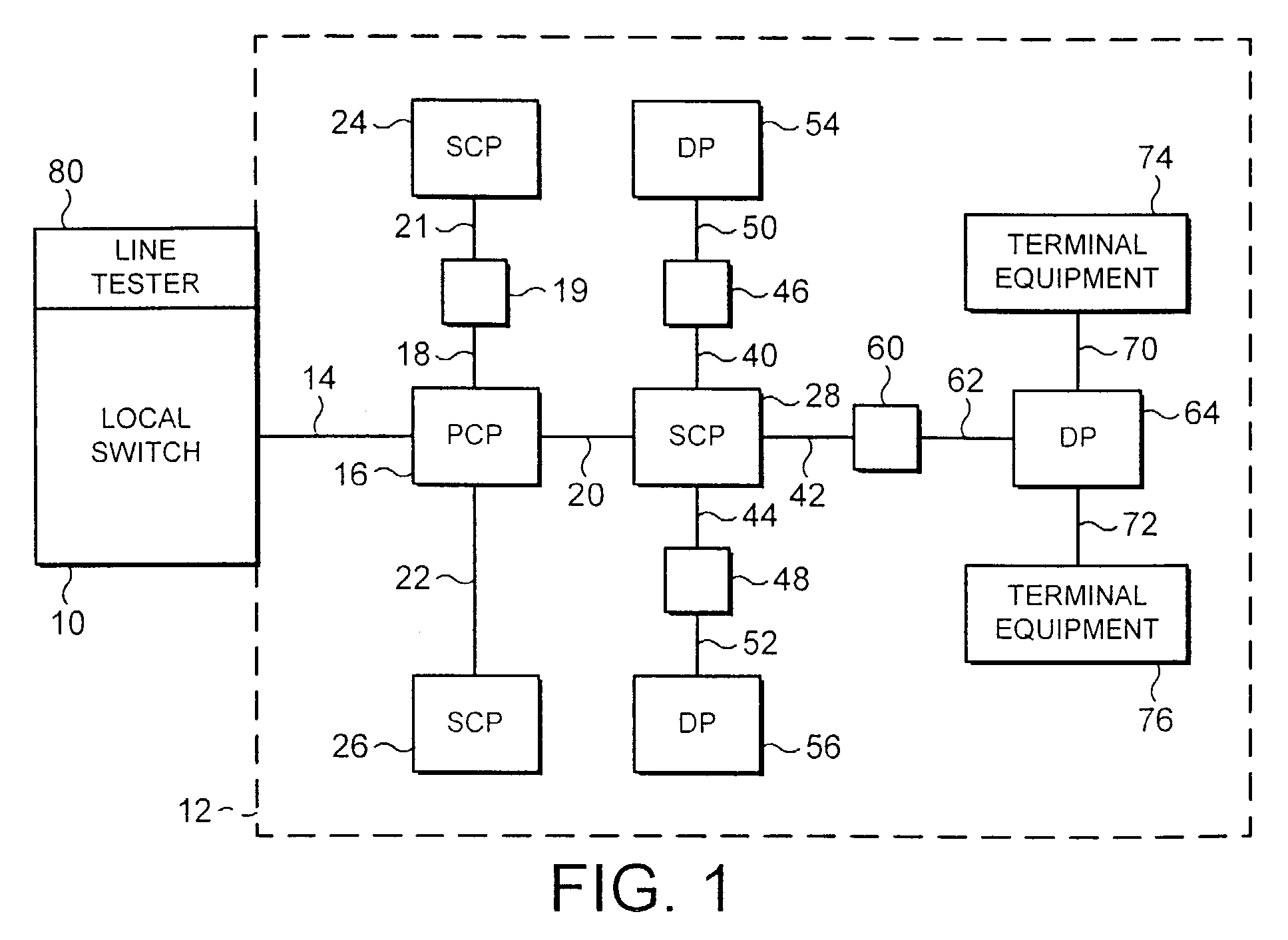
[0039]FIG. 1 illustrates an access network 12 of a conventional telecommunications network connected to a local switch 10. The local switch 10 and the access network 12 form part of a telecommunications network.

[0040]The local switch 10 is connected to the terminating line of the access network 12. Typically, a local switch is connected to several thousand terminating lines. Each terminating line passes through several nodes before reaching its respective terminal equ...


PUM


Abstract

A fault location system for a telecommunications network including a local exchange or switch, a node such as a primary connection point and a plurality of line terminations includes probability calculation to establish the location of a fault measured from the exchange. Historical non-faulty reference values of capacitance are compiled for each line passing through the node providing a measure of the distance of each line. A lowest valid capacitance value provides an estimate of the reference capacitance between the exchange and the node. A histogram is compiled of historic fault values and a new fault is compared against the histogram to establish the probability of it being a fault at the node or elsewhere. As a result the reference capacitance can be obtained without the need for an engineer at the node, and the likely location of a fault can be pinpointed with greater accuracy.

Description

[0001]This application is the US national phase of international application PCT / GB01 / 00952 filed 5 Mar. 2001 which designated the U.S.BACKGROUND[0002]1. Technical Field[0003]The invention relates to a method of locating faults on a telecommunications network, a method of compiling a distribution of historic parameter values for such a method, and a fault locating system.[0004]2. Related Art[0005]A conventional public telecommunications network comprises a relatively small number of interconnected main switches and a larger number of local switches, each of which is connected to one or two main switches. The local switches are connected to the terminating lines of the network and the far ends of these lines are connected to terminal equipment such as telephone instruments provided for users of the network.[0006]The network formed from the main switches and local switches is known as the core network, while the network formed from the terminating lines is known variously as an access...

Claims


Application Information

Patent Timeline
Patent Type & Authority Patents(United States)
IPC IPC(8): G01R31/08H04M3/08H04M3/30H04M3/36
CPCH04M3/30H04M3/085H04M3/305H04M3/36
Inventor LUNT, NICHOLASLOGAN, HILARY PCHATTELL, ANDREW D
Owner BRITISH TELECOMM PLC
Why Eureka
Try Eureka