Apparatus and method for measuring and compensating delay between main base station and remote base station interconnected by an optical cable

a technology of optical cable and delay measurement, applied in the field of synchronous mobile communication system, can solve the problems of relative large delay between the main base station and the remote base station, degraded speech quality of the mobile unit, errors can be incurred,

Inactive Publication Date: 2008-04-15
SAMSUNG ELECTRONICS CO LTD
View PDF5 Cites 118 Cited by
  • Summary
  • Abstract
  • Description
  • Claims
  • Application Information

AI Technical Summary

Benefits of technology

[0017]It is another object of the present invention to provide an apparatus and method for detecting frame al...

Problems solved by technology

When the main base station and the remote base stations are separated by the relatively long distance of several to several tens of kilometers, the time period required for transmitting a forward baseband signal from the main base station to the remote base stations is proportional to the distance, and relatively large time delays can be incurred between the main base station and the remote base stations.
The different time delays can cause RF signals from the remote base stations to be asynchronously transmitted.
In particular, when a mobile unit communicates with a plurality of remote base stations, the problem of asynchronization between the base and the remote base stations can cause speech quality of the mobile unit to be degraded.
When the remote base stations are not synchronized in the synchronous CDMA system, errors ...

Method used


Image

  • Apparatus and method for measuring and compensating delay between main base station and remote base station interconnected by an optical cable
  • Apparatus and method for measuring and compensating delay between main base station and remote base station interconnected by an optical cable
  • Apparatus and method for measuring and compensating delay between main base station and remote base station interconnected by an optical cable

Examples


Embodiment Construction

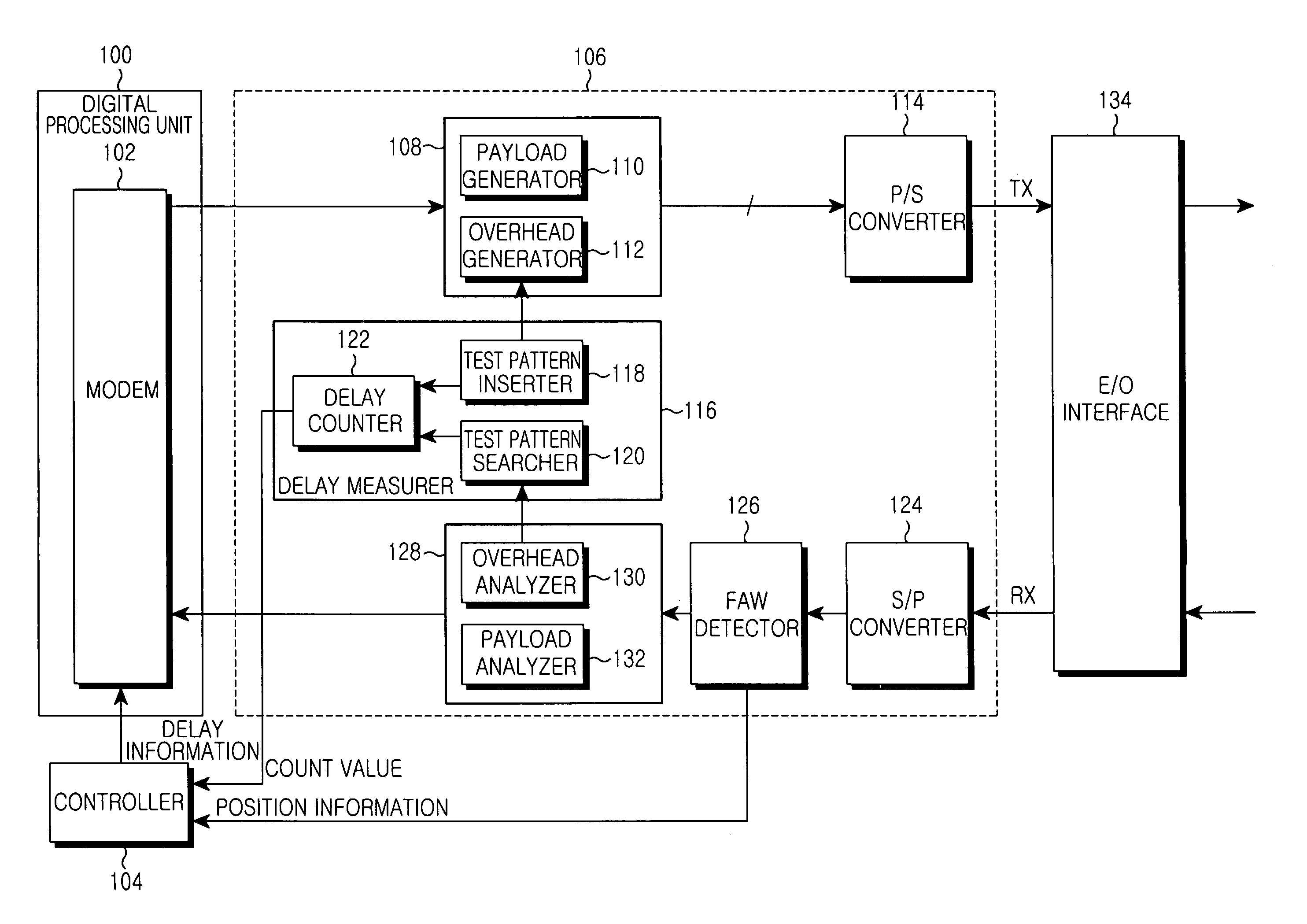
[0034]Now, preferred embodiments of the present invention will be described in detail with reference to the annexed drawings. In the drawings, the same or similar elements are denoted by the same reference numerals even though they are depicted in different drawings. In the following description, a detailed description of known functions and configurations incorporated herein will be omitted when it may make the subject matter of the present invention rather unclear. The words or expressions to be described below are defined on the basis of functions associated with the embodiments of the present invention. The defined words or expressions can be changed according to intentions or usual practices of a user or a chip designer. Thus, the words or expressions are defined by the entire contents of the present invention.

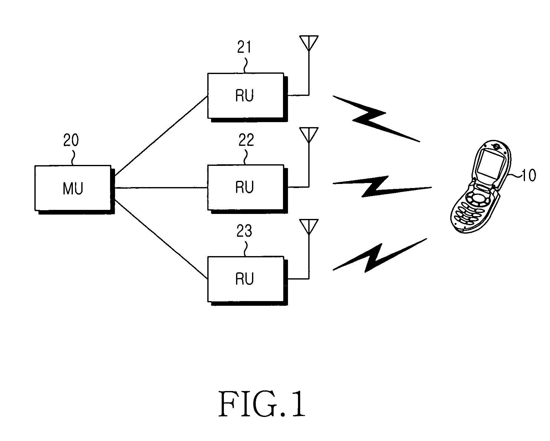
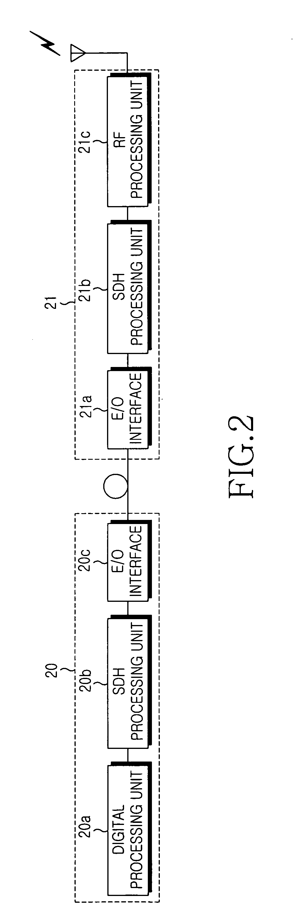
[0035]The embodiments of the present invention described below synchronizes remote base stations connected to a main base station through optical cables using a synchrono...


PUM


Abstract

An apparatus and method for measuring and compensating for delay between a main base station and a remote base station interconnected by an optical cable. The main base station inserts a test pattern into an overhead part of an SDH frame to transmit the SDH frame to the remote base station, receives the SDH frame looped back by the remote base station to detect the test pattern, and measures propagation delay according to the test pattern. At least one frame alignment word (FAW) is detected at a predetermined position in the received SDH frame, and a delay error is calculated according to FAW detection information. The measured propagation delay with the delay error is compensated and produces propagation delay caused by the optical cable. A modulator/demodulator (MODEM) compensates for delay of a baseband signal to be transmitted to the remote base station.

Description

PRIORITY[0001]This application claims priority to an application entitled “APPARATUS AND METHOD FOR MEASURING AND COMPENSATING DELAY BETWEEN MAIN BASE STATION AND REMOTE BASE STATION”, filed in the Korean Intellectual Property Office on Jan. 30, 2003 and assigned Serial No. 2003-6427, the contents of which are hereby incorporated by reference.BACKGROUND OF THE INVENTION[0002]1. Field of the Invention[0003]The present invention relates to a synchronous mobile communication system, and more particularly to an apparatus and method for measuring and compensating delay between a main base station and a remote base station interconnected by an optical cable.[0004]2. Description of the Related Art[0005]A cellular mobile communication system divides an entire service area into a plurality of cells and covers the cells using base stations. An overlay cell can be formed between adjacent cells in an actual wireless environment. A user mobile unit can receive signals from at least two base stat...

Claims


Application Information

Patent Timeline
IPC IPC(8): H04Q7/30H04B17/00H04B10/2507H04B10/2575H04J3/00H04W24/00H04W88/08H04W92/00
CPCH04B10/25754H04J3/0682H04J3/0602H04J2203/0041H04W88/085H04B17/00
Inventor KIM, KYOU-SEUNG
Owner SAMSUNG ELECTRONICS CO LTD
Why Eureka
Try Eureka