Method of and device for re-calibrating three-dimensional visual sensor in robot system

a three-dimensional visual sensor and robot system technology, applied in the direction of distance measurement, programme control, computer control, etc., can solve the problems of lowering the measurement accuracy, and unable to accurately measure, so as to achieve the effect of recalibration with ease and short tim

Inactive Publication Date: 2008-04-15
FANUC LTD
View PDF28 Cites 33 Cited by
  • Summary
  • Abstract
  • Description
  • Claims
  • Application Information

AI Technical Summary

Benefits of technology

[0011]According to the present invention, data obtained while a three-dimensional visual sensor is capable of normal measurement is used so that re-calibration can be performed easily without the need to repeat calibration work all over again, thereby mitigating the work load required for the re-calibration.
[0064]According to the present invention, the three-dimensional visual sensor can be recalibrated with ease. Specifically, at the time of re-calibration, it is unnecessary to use a calibration jig for accurately reproducing the relative positional relation between the three-dimensional visual sensor and the measurement target, and the re-calibration is achieved using the position data (obtained during normal measurement) and feature amounts (obtained during re-calibration) of the measurement target acquired at the same robot position. Accordingly, the re-calibration does not require the labor and time for attaching and detaching the calibration jig, unlike the conventional techniques, and the three-dimensional visual sensor can be restored to its normal state in a very short time.

Problems solved by technology

Thus, various calibration methods for three-dimensional visual sensors are conventionally known, but it is often the case that after proper measurement accuracy is once obtained by calibration, the measurement accuracy lowers, making accurate measurement impossible.
Also, even if the apparent position of the sensor is not displaced, the arrangement of the internal optical system may possibly change from that at the time of calibration due to an impact or the like, causing lowering of the measurement accuracy.
To again perform the identical calibration work, however, it is necessary that the relative positional relation between a measurement target and the visual sensor should be accurately reproduced by again using a calibration jig, requiring a heavy work load and inevitably prolonging the system downtime.

Method used


Image

  • Method of and device for re-calibrating three-dimensional visual sensor in robot system
  • Method of and device for re-calibrating three-dimensional visual sensor in robot system
  • Method of and device for re-calibrating three-dimensional visual sensor in robot system

Examples


Embodiment Construction

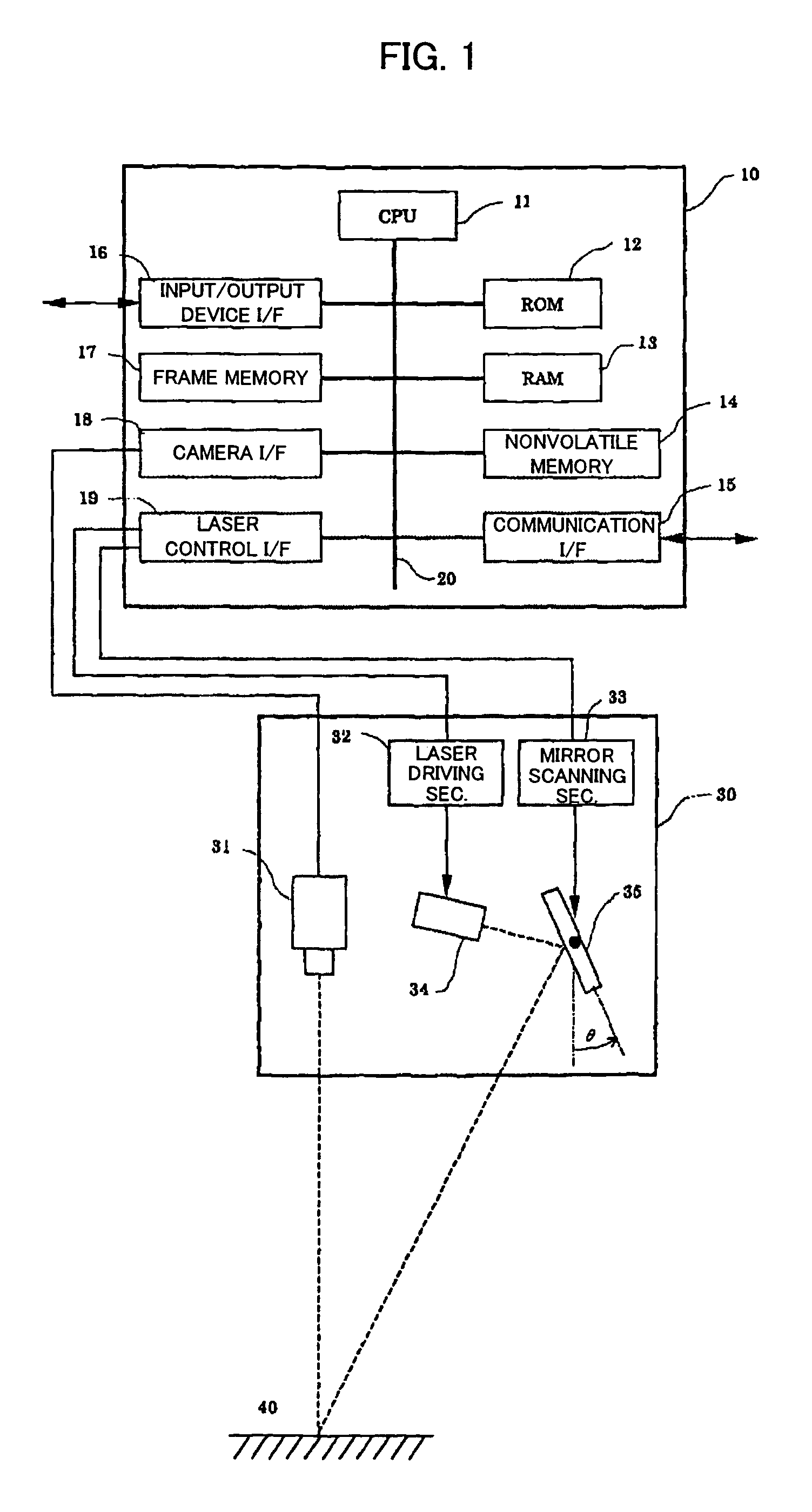
[0077]FIG. 1 shows the configuration of a principal part of a three-dimensional visual sensor (hereinafter also referred to merely as “visual sensor”) used in an embodiment of the invention. The illustrated visual sensor itself is a typical one well known in the art, and comprises a sensor head 30 including an optical system and optical detection means for measuring an object, and a three-dimensional visual sensor controller 10 for controlling the sensor head 30 and processing information related to three-dimensional measurement. In the sensor head 30 are arranged a laser beam emitter 34, a laser driving section 32 for driving the emitter, a mirror 35 for scanning an object with the laser beam, and a mirror scanning section 33 for driving the mirror. The sensor head is also equipped with a camera 31 for acquiring a two-dimensional image of an object 40 and receiving the reflection of the laser beam irradiated onto the object 40.

[0078]On the other hand, the three-dimensional visual s...


PUM


Abstract

A re-calibration method and device for a three-dimensional visual sensor of a robot system, whereby the work load required for re-calibration is mitigated. While the visual sensor is normal, the visual sensor and a measurement target are arranged in one or more relative positional relations by a robot, and the target is measured to acquire position / orientation information of a dot pattern etc. by using calibration parameters then held. During re-calibration, each relative positional relation is approximately reproduced, and the target is again measured to acquire feature amount information or position / orientation of the dot pattern etc. on the image. Based on the feature amount data and the position information, the parameters relating to calibration of the visual sensor are updated. At least one of the visual sensor and the target, which are brought into the relative positional relation, is mounted on the robot arm. During the re-calibration, position information may be calculated using the held calibration parameters as well as the feature amount information obtained during normal operation of the visual sensor and that obtained during the re-calibration, and the calibration parameters may be updated based on the calculation results.

Description

BACKGROUND OF THE INVENTION[0001]1. Field of the Invention[0002]The present invention generally relates to an industrial robot system including a three-dimensional visual sensor, and more particularly to a method of re-calibrating a three-dimensional visual sensor and a device for carrying out the re-calibration method.[0003]2. Description of Related Art[0004]Three-dimensional visual sensors are widely used in various applications employing robot systems. Usage of three-dimensional visual sensors can be classified roughly into the following two cases (i) and (ii).[0005](i) A three-dimensional visual sensor is used with its sensor head mounted on a robot arm. The sensor head denotes a sensor section having an optical system (including an optical detector) for measuring an object, and control of the sensor head and processing of the detection signal are performed by a visual sensor controller. In this specification, the expression “mounting a three-dimensional visual sensor on a robot...

Claims


Application Information

Patent Timeline
Patent Type & Authority Patents(United States)
IPC IPC(8): G06F19/00G01C25/00G05B99/00B25J13/08G01B11/00G01B11/26
CPCB25J9/1692G01B21/042
Inventor BAN, KAZUNORIKANNO, ICHIRO
Owner FANUC LTD
Why Eureka
Try Eureka