Apparatus for detecting pressure

a technology for internal combustion engines and apparatuses, applied in the direction of machines/engines, electric control, instruments, etc., can solve the problems of increasing the stress on the engine structure, reducing the efficiency of the engine, and many internal combustion engines operating in relatively high temperatures

Active Publication Date: 2008-04-22
WARTSILA FINLAND OY
View PDF15 Cites 28 Cited by
  • Summary
  • Abstract
  • Description
  • Claims
  • Application Information

AI Technical Summary

Benefits of technology

[0009]The invention is based on the idea that there is no need for an accurate measurement of pressure. What must actually be known is the moment the fuel pressure exceeds a certain pre-determined level. A simple on-off-detector will be sufficient for this. Such an inventive detector can be produced by allowing the pressure to cause a switching operation when the pressure exceeds a certain limit. Detecting the switching operation still allows the desired operations to be carried out, such as correcting the timing of the fuel injection. A simple operation can be carried out by means of a solution that's simple yet durable in the conditions.

Problems solved by technology

In addition, many internal combustion engines operate in relatively high temperatures.
A problem with these systems is that as there is wear on the engine during operation, the set values of the electronics no longer correspond with the changed conditions in the engine, whereby the engine runs on a decreased efficiency, causing more stresses on the structure of the engine.
Detecting the fuel pressure by means of pressure sensors is possible, but such apparatuses are expensive.
There are a number of pressure sensors available on the market, but as the sensor must be able withstand a pressure of over 1000 bar in a temperature of over 100 degrees, there are hardly any commercial solutions at a reasonable price, and therefore they are not used.
A problem with this sensor is that the dimensioning for a low operation range (operating at a pressure of, for example, about 20 bar) and a simultaneous requirement for high maximum pressure (e.g. about 1500 bar) is very difficult, if not impossible, to carry out.
Another challenge is the operation in a temperature of over 100 degrees.
These applications are expensive as well.

Method used


Image

  • Apparatus for detecting pressure
  • Apparatus for detecting pressure

Examples


Embodiment Construction

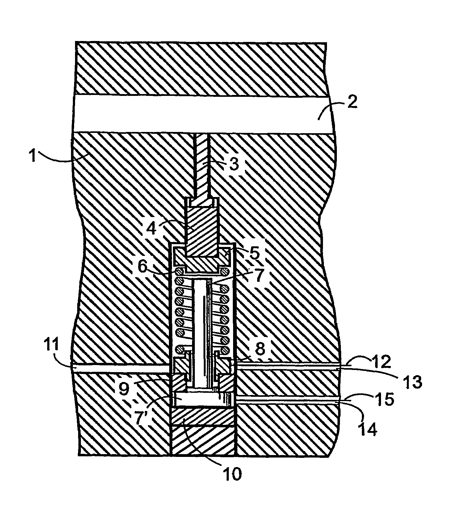
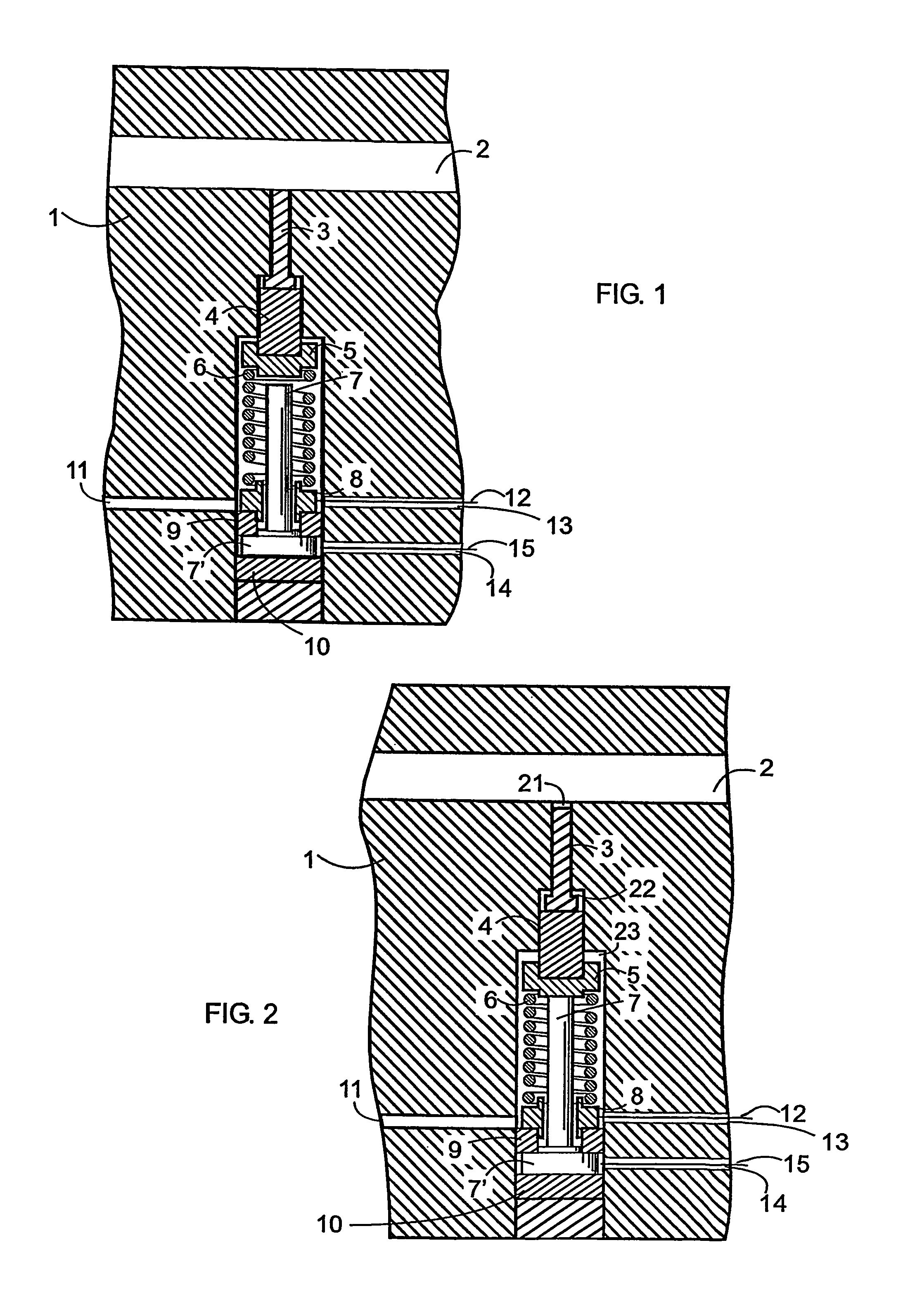
[0019]FIG. 1 illustrates an example of an apparatus according to the invention with the apparatus in rest mode, i.e. with the switch formed by the apparatus open. The piston 3 of the apparatus is in connection to volume 2 containing high-pressure fuel. In this example the body structure 1 of the apparatus is integral with the surrounding structure (e.g. when the spaces required by the apparatus are bored in the desired place in the engine structure). It is, however, also possible that the structure is a separate structure connected to the surrounding structure.

[0020]The lower end of the piston is in connection to the intermediate part 4 being in connection to the upper support 5 of the spring 6 of the apparatus. The clearance between the intermediate part and the body is large, whereby great heat expansion differences do not hinder the operation. The intermediate part is to transfer the movement of the piston to the upper support of the spring and to prevent contact between the uppe...


PUM

PropertyMeasurementUnit
pressureaaaaaaaaaa
temperatureaaaaaaaaaa
pressureaaaaaaaaaa

Abstract

The present invention relates to apparatuses for detecting fuel pressure in internal combustion engines. The invention especially relates to internal combustion engine applications in which fuel reaches a high pressure. The apparatus according to the invention is a simple switch apparatus. In the apparatus the fuel pressure moves a piston causing a switching operation in the apparatus, which in turn can be detected by means of a separate detector.

Description

[0001]This is a national stage application filed under 35 USC 371 based on International Application No. PCT / FI2004 / 000690 filed Nov. 17, 2004, and claims priority under 35 USC 119 of Finnish Patent Application No. 20031850 filed Dec. 18, 2003.TECHNICAL FIELD[0002]The present invention relates to apparatuses for detecting fuel pressure in internal combustion engines. The invention specially relates to internal combustion engine applications in which fuel reaches a high pressure. The invention additionally relates to applications in which the fuel is heavy fuel oil.PRIOR ART[0003]In many fuel injection systems of combustion engines it is necessary to know when the pressure starts to rise (beginning of injection). For example, in so-called Common Rail systems the fuel pressure is increased to about 1500 bar before the fuel is injected into the combustion chamber via the injector nozzle. The pressure information is needed in order to have the fuel injected in the cylinder at the right ...

Claims


Application Information

Patent Timeline
Patent Type & Authority Patents(United States)
IPC IPC(8): G01L7/16G01L9/00H01H35/38
CPCG01L9/0089H01H35/38F02D2200/0602G01L7/00F02D41/38G01L9/00G01L7/16
Inventor LEHTONEN, KAI
Owner WARTSILA FINLAND OY
Why Eureka
Try Eureka