Spray gun

a spray gun and spray technology, applied in the field of spray guns, can solve the problems of significant flow noise, inadequate cooling, and spray guns that do not provide a reasonable level of efficiency

Active Publication Date: 2008-04-22
J WAGNER GMBH
View PDF15 Cites 43 Cited by
  • Summary
  • Abstract
  • Description
  • Claims
  • Application Information

AI Technical Summary

Problems solved by technology

This generates significant flow noise as well as flow losses, therefore this spray gun does not provide a reasonable level of efficiency.
A further disadvantage is that the drive motor of the air turbine is only provided with inadequate cooling; this is because the only air flowing past the drive motor is the air drawn in by the air turbine and this air flow is not controlled, meaning that sustained operation is often impossible.
Also, this spray gun does not provide any counterbalance because the reservoir conta

Method used


Image

  • Spray gun
  • Spray gun
  • Spray gun

Examples


Embodiment Construction

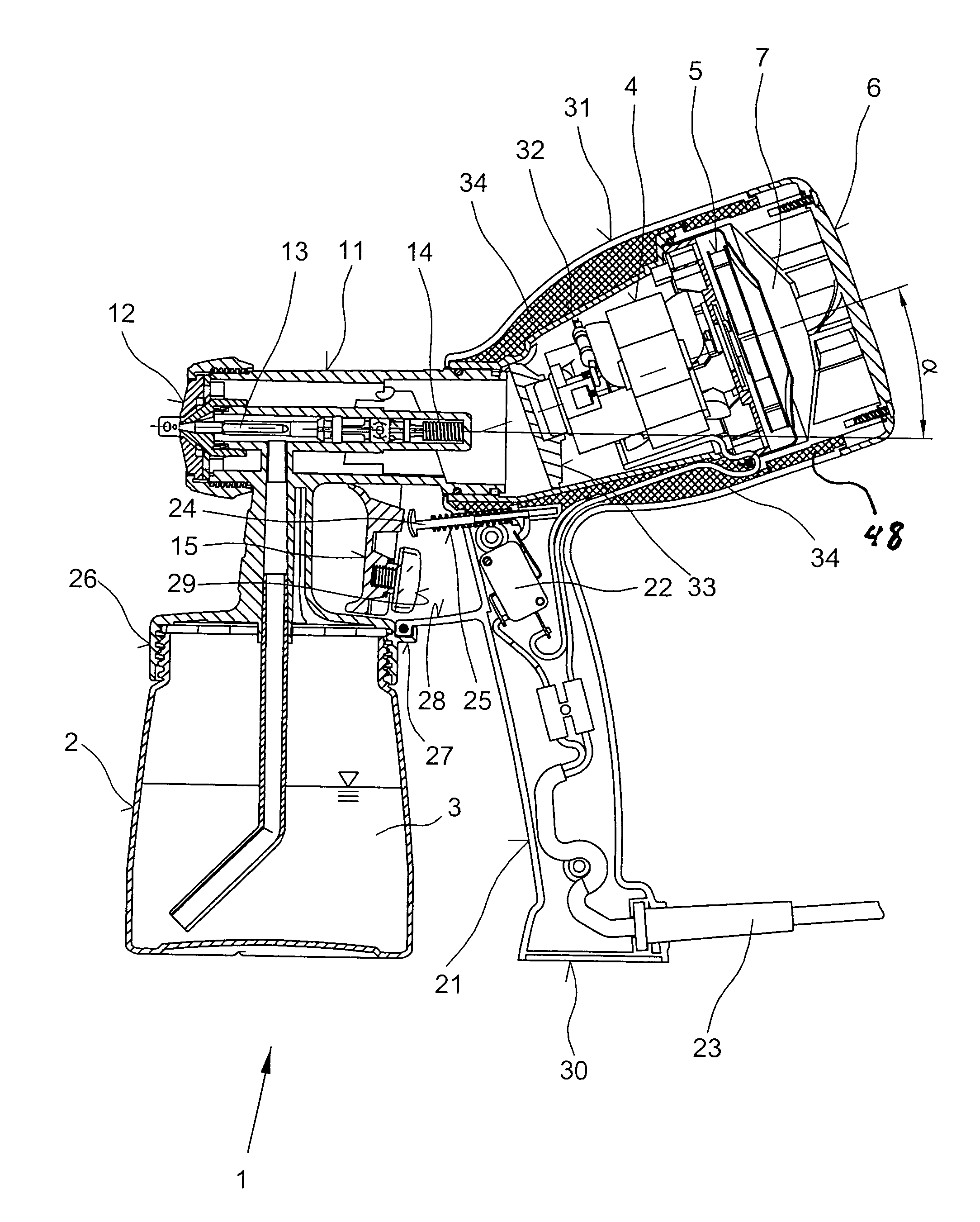
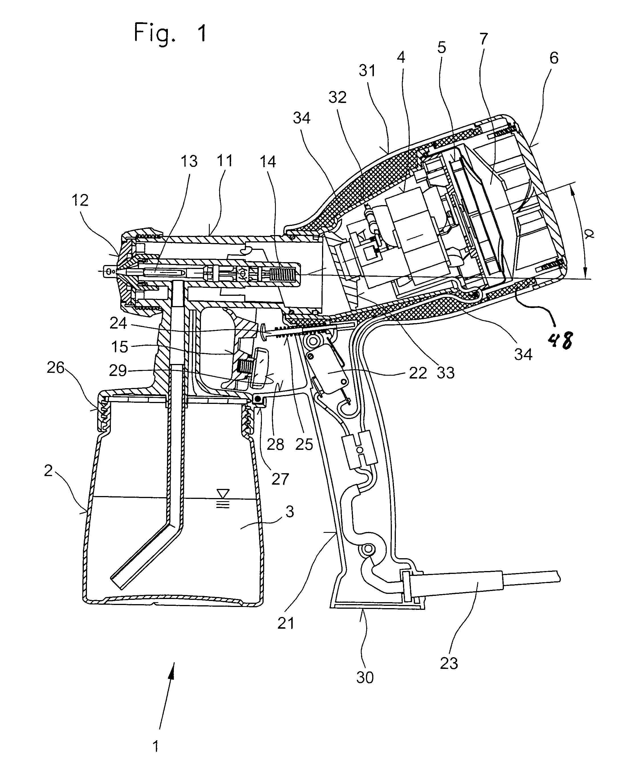
[0037]The spray gun shown in FIGS. 1, 2, 3 and 4 and identified with 1 or 1′ is used for atomising paints, lacquers or similar media 3 located in a reservoir container 2, it being possible to supply the media 3 to a workpiece by means of an air flow. In the illustrated embodiment, the air flow for atomisation is generated by an air turbine 5 that can be driven by an electric motor 4. In addition, the air turbine 5 is provided with a muffler 6 in order to reduce the intake noise, whilst a cavity 7 is created between the muffler 6 and the air turbine 5 for the same purpose.

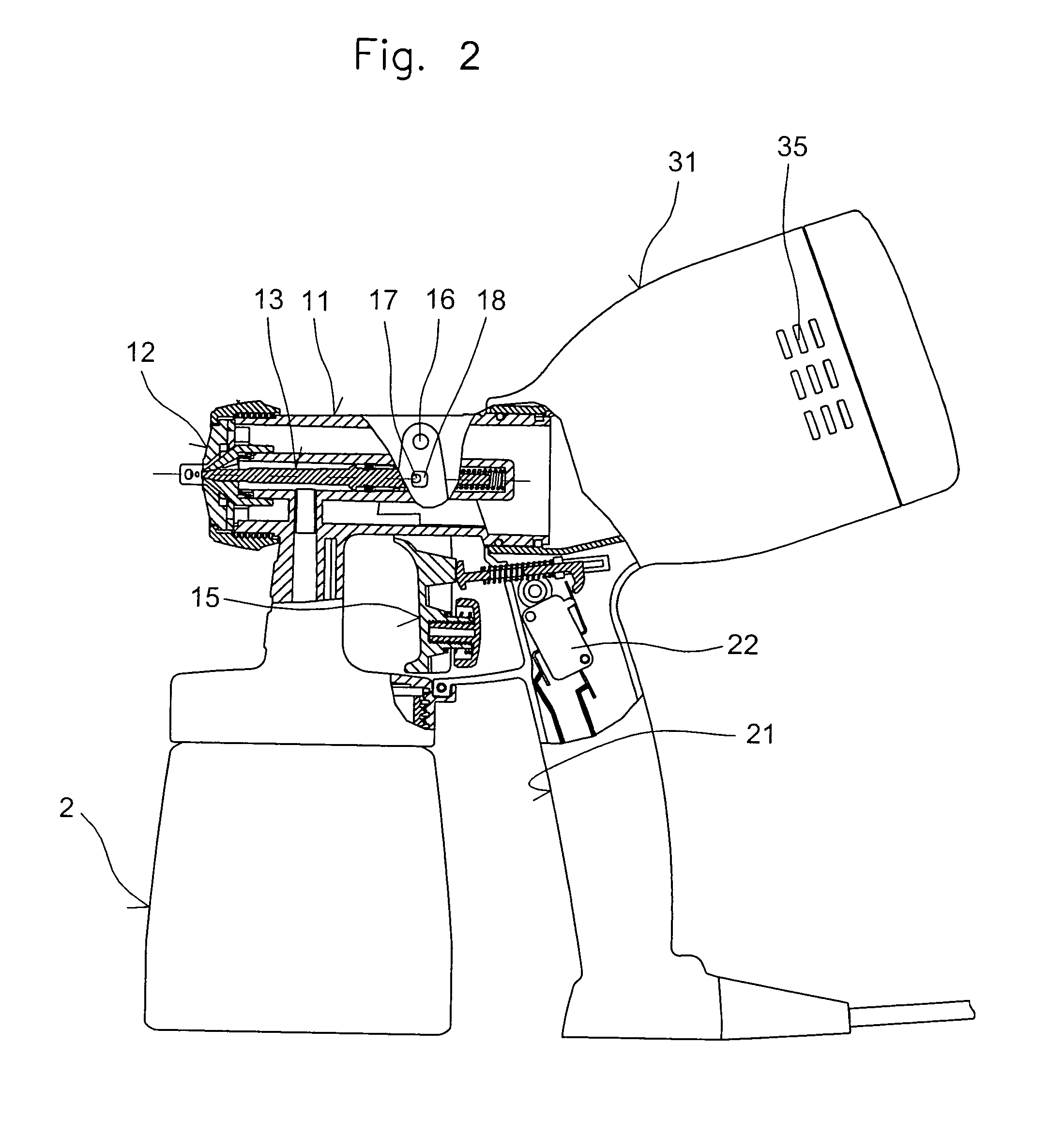
[0038]The spray gun 1 principally consists of a sleeve 11 to which the reservoir container 2 is attached, of an atomiser nozzle 12 equipped with an axially adjustable nozzle needle 13 and also attached to the sleeve 11, of a handle 21 and of an attachment 31 formed onto the handle 21, the attachment 31 being firmly connected to the sleeve in the case of the spray gun 1 and which accommodates the air turbine 5, its d...


PUM


Abstract

In a spray gun (1) for atomizing fluids, that can be actuated using a lever (15) mounted in a pivoting arrangement on a sleeve (11) which accommodates an atomizer nozzle (12) and in which the air flow can be generated by an air turbine (5) that is assigned to the spray gun (1), the air turbine (5) and its electric drive motor (4) are arranged substantially coaxially to the sleeve (11) on the opposite side of a handle (21) and the air flow is supplied from the air turbine (5) in a substantially straight line through the sleeve (11) of the atomizer nozzle (12). The air turbine (5) is provided with a muffler (6). Loud operating noise of the air turbine (5) does not have a disruptive effect and practically no flow noise is generated due to deflections of the air flow. The components of the spray gun (1) are arranged in such a way that no more than slight tilting torques are generated, permitting work over long periods without leading to fatigue.

Description

BACKGROUND OF THE INVENTION[0001]1. Field of the Invention[0002]The present invention relates to a spray gun for atomizing paints, lacquers or similar media that can be supplied to a workpiece by means of an air flow, in which case the spray gun can be actuated by means of a lever mounted in a pivoting arrangement on a sleeve which accommodates an atomiser nozzle and the air flow can be generated by an air turbine assigned to the spray gun.[0003]2. Description of the Prior Art[0004]A spray gun of this type is described in FR 80 145 66. In this embodiment, the electric motor driving the air turbine can be removed together with the air turbine and is arranged in a separate component on the housing of the spray gun perpendicular to the atomizer nozzle of the spray gun, so that the air flow generated by the air turbine has to have its direction changed several times before it emerges from the atomizer nozzle.[0005]This generates significant flow noise as well as flow losses, therefore t...

Claims


Application Information

Patent Timeline
IPC IPC(8): B05B7/30B05B1/28B05B7/24
CPCB05B7/2416
Inventor GOHRING, ALFREDIBELE, PETERKRAMER, ANDREASULBRICH, JENS
Owner J WAGNER GMBH
Why Eureka
Try Eureka