Lock assembly

a technology for locking mechanisms and doors, applied in the field of locking mechanisms, can solve the problems of excessive machining and adjustment requirements, high stress on sprag biasing means, inconvenience for passengers and operation schedule delays, etc., and achieve the effect of increasing the reliability of operation

Active Publication Date: 2008-04-22
WABTEC HLDG CORP
View PDF5 Cites 47 Cited by
  • Summary
  • Abstract
  • Description
  • Claims
  • Application Information

AI Technical Summary

Benefits of technology

[0019]It is, therefore, one of the primary objects of the present invention to provide an improved lock mechanism for a passenger vehicle which selectively locks and unlocks a door of the passenger vehicle.
[0020]It is another object of the present invention to provide an improved lock mechanism for a passenger vehicle which has a manual release means for manual unlocking of the door.
[0021]It is yet another object of the present invention to provide an improved lock mechanism for a passenger transit vehicle which increases reliability of operation.
[0022]It is a further object of the present invention to provide an improved lock mechanism for a passenger vehicle which utilizes less moving components.
[0023]It is additional object of the present invention to provide an improved lock mechanism for a passenger vehicle which selectively locks and unlocks a pair of bi-parting doors.

Problems solved by technology

Failure of the lock mechanism to reliably disengage from the door will result in passenger inconvenience and operational schedule delays.
It has also been found that incorporation of such plurality of rollers, additional machining and adjustment requirements excessively increased lock mechanism cost.
Additionally, it has been found that the sprag biasing means are subjected to high stresses due to spatial limitations within passenger vehicle structure and resulting configuration of the base member.

Method used


Image

  • Lock assembly
  • Lock assembly
  • Lock assembly

Examples


Embodiment Construction

, particularly, when the detailed description is taken in conjunction with the attached drawing figures and with the appended claims.

BRIEF DESCRIPTION OF THE DRAWINGS

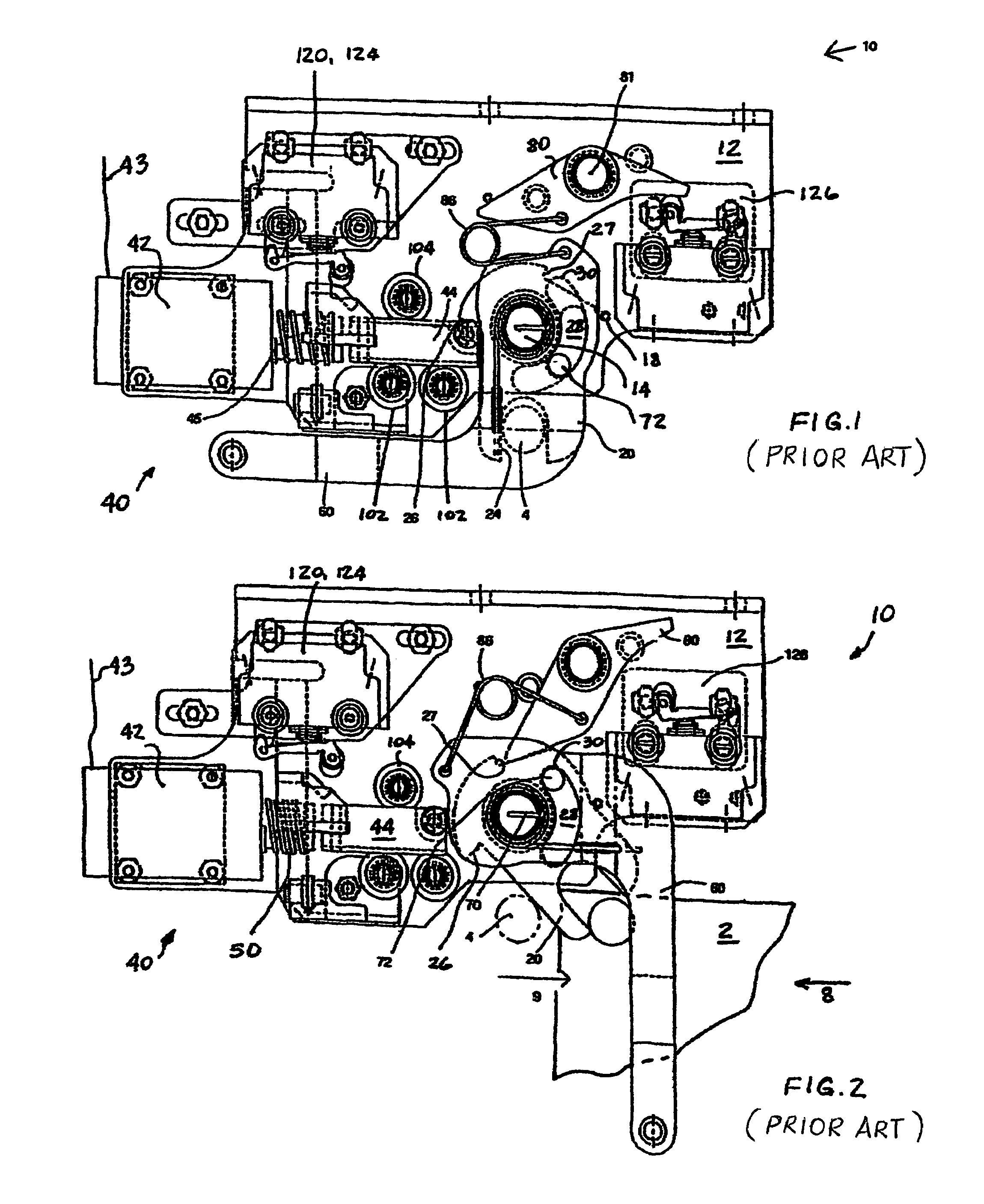
[0026]FIG. 1 is a plan view of a prior art lock mechanism particularly showing the lock cam engaging the locking element on the door as the door is in a locked position;

[0027]FIG. 2 is a plan view of the prior art lock mechanism illustrated in FIG. 1 showing a manual release lever in a fully rotated position enabling manual unlocking of the door;

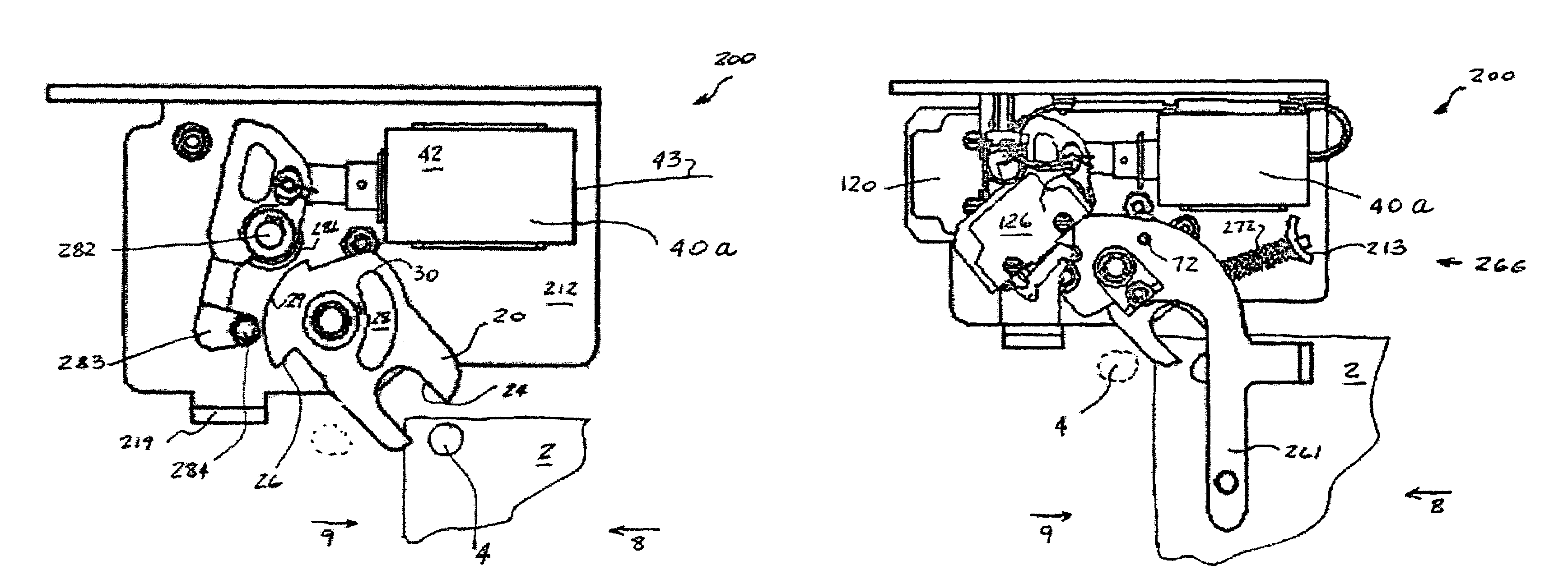
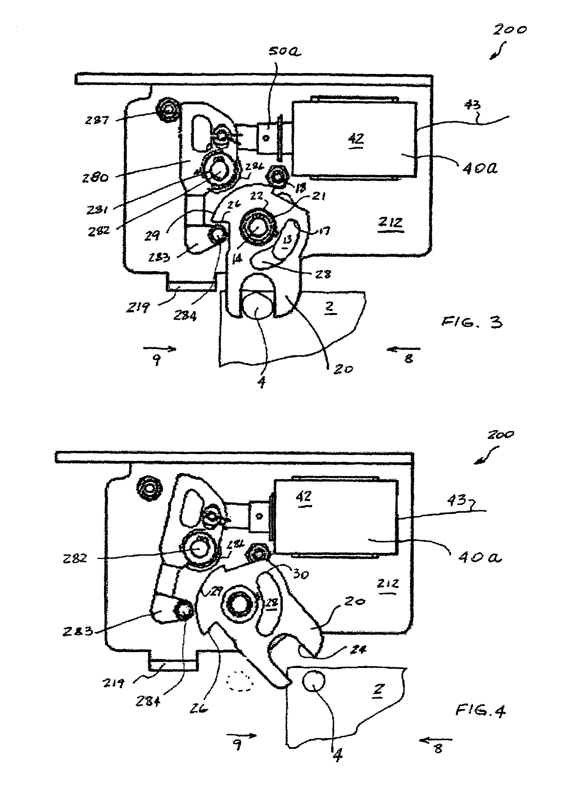
[0028]FIG. 3 is a plan view of a lock mechanism of a first embodiment of the present invention, particularly showing the lock cam engaging the locking element on the door in a locked position;

[0029]FIG. 4 is a a plan view of the lock mechanism of the present invention of FIG. 3, particularly showing the lock cam and the locking element in an unlocked position;

[0030]FIG. 5 is a plan view of the lock mechanism of the present invention particularly showing a manual release lever in...


PUM


Abstract

A lock mechanism for locking and unlocking a door in a passenger vehicle includes a lock cam pivotally connected to a base member. The lock cam has a slot for engaging a lock pin attached to the door. A pivotally connected lock lever engages the lock cam for biasing it and the door lock element in the locked position. An actuator is attached to the base member and connected to the lock lever for releasing the lock lever from engagement with the lock cam enabling the door to unlock. The actuator is connectable with a door control system for receiving a release signal. A manual release is connected to the lock mechanism to manually release the lock cam from engagement with the lock lever. A toggle mechanism biases the manual release in the unlock position and returns it into the lock position. A second pair of lock cam and lock lever may be provided for locking and unlocking a second door in the passenger vehicle.

Description

CROSS-REFERENCE TO RELATED APPLICATIONS[0001]This application is related to U.S. Pat. No. 6,139,073 entitled “Lock Assembly” and owned by the assignee of the present invention. The teaching of U.S. Pat. No. 6,139,073 is incorporated into this document by reference thereto.FIELD OF THE INVENTION[0002]The present invention relates, in general, to lock mechanisms for locking a movable object and, more particularly, this invention relates to lock mechanisms for locking a door of a vehicle and, yet more particularly, the instant invention relates to a lock mechanism for locking at least one door of a passenger transit vehicle.BACKGROUND OF THE INVENTION[0003]The following background information is provided to assist the reader in understanding the environment in which the invention will typically be used. The terms used herein are not intended to be limited to any particular narrow interpretation unless specifically stated otherwise in this document.[0004]The present invention will be di...

Claims


Application Information

Patent Timeline
Patent Type & Authority Patents(United States)
IPC IPC(8): E05C3/06
CPCE05B81/14E05B85/26E05B77/50E05B85/247E05B81/90Y10T292/0922Y10T292/1047
Inventor PARENT, PASCALFILION, DANIEL
Owner WABTEC HLDG CORP
Why Eureka
Try Eureka