
Drip molding for vehicle, having furnishing lip part bending toward windowpane

a technology of lip molding and windowpane, which is applied in the direction of roofs, transportation and packaging, vehicle arrangements, etc., can solve the problems of difficult simultaneous operation, difficult to sufficiently suppress the turbulent flow on the outer face of the pillar, and wind-cutting sound, and achieve the effect of sufficient capacity of drainage path and width of outer fa

Inactive Publication Date: 2008-04-22
HONDA MOTOR CO LTD
View PDF4 Cites 9 Cited by
  • Summary
  • Abstract
  • Description
  • Claims
  • Application Information

AI Technical Summary

Benefits of technology

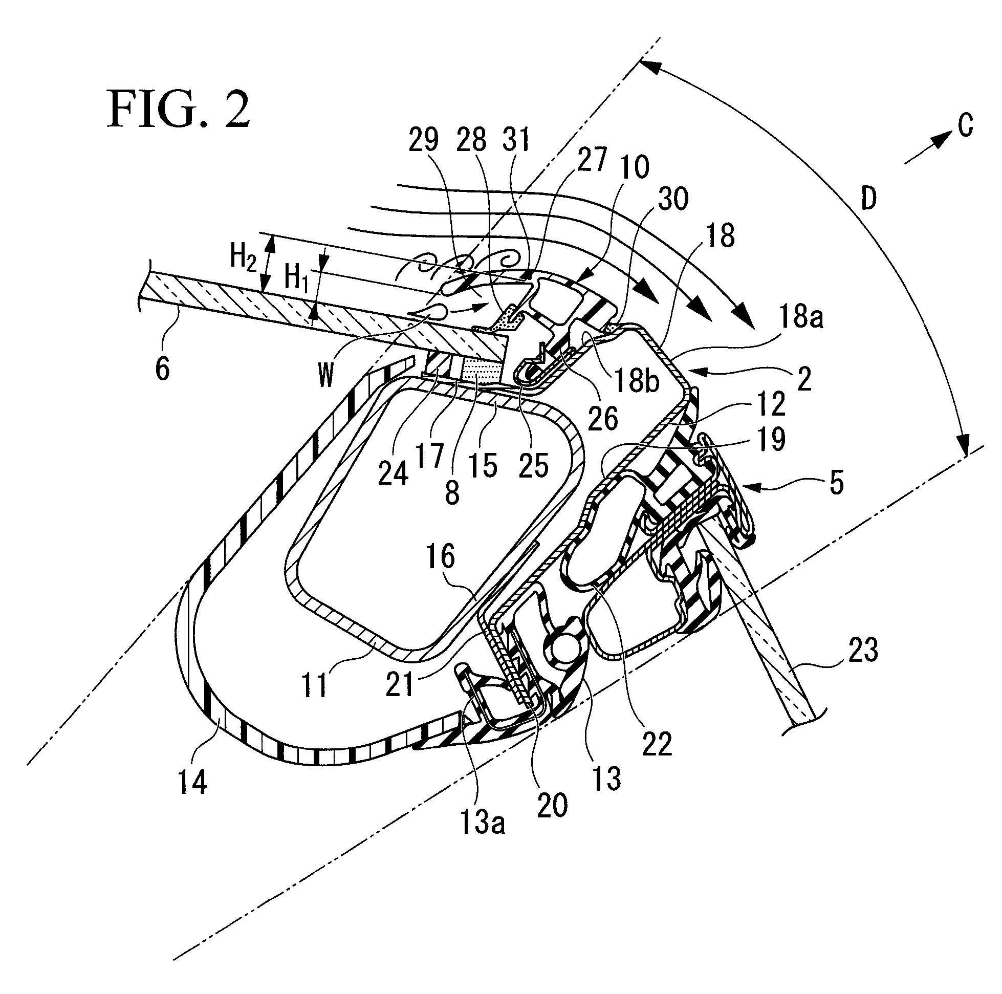
The present invention provides a drip molding for a vehicle that can secure a sufficient capacity of a drainage path without producing a wind-cutting sound, even when the width of the outer face of the pillar is restricted. The drip molding includes an attachment base, a glass pane sealing part, and a furnishing lip part. The furnishing lip part has a canopy shape and a bent surface that functions as a current adjusting surface for an air current flowing from the front surface of the windowpane toward the relevant side of the vehicle body. The drip molding can be put in close contact with the windowpane and the pillar via the flexible parts, and the shape of the drip molding can be accurately arranged between the pillar and the windowpane. The invention provides a solution for preventing wind-cutting sounds and ensuring a sufficient capacity of the drainage path.

Problems solved by technology

Additionally, when this distance increases, part of the air current drawn from the front surface of the windowpane to either side of the vehicle body is separated at the furnishing lip part, which tends to cause a wind-cutting sound.
In this case, it is difficult to sufficiently suppress the turbulent flow on the outer face of the pillar.
Therefore, actually, it is difficult to simultaneously: (i) secure a sufficient capacity of the drainage path; and (ii) prevent the occurrence of a wind-cutting sound.

Method used


Image

  • Drip molding for vehicle, having furnishing lip part bending toward windowpane
  • Drip molding for vehicle, having furnishing lip part bending toward windowpane
  • Drip molding for vehicle, having furnishing lip part bending toward windowpane

Examples


Embodiment Construction

[0032]Hereinafter, an embodiment in accordance with the present invention will be described with reference to the appended figures. In the following explanation, the terms “front” and “back” are defined with respect to the direction in which a vehicle runs, unless another specific explanation thereof is added.

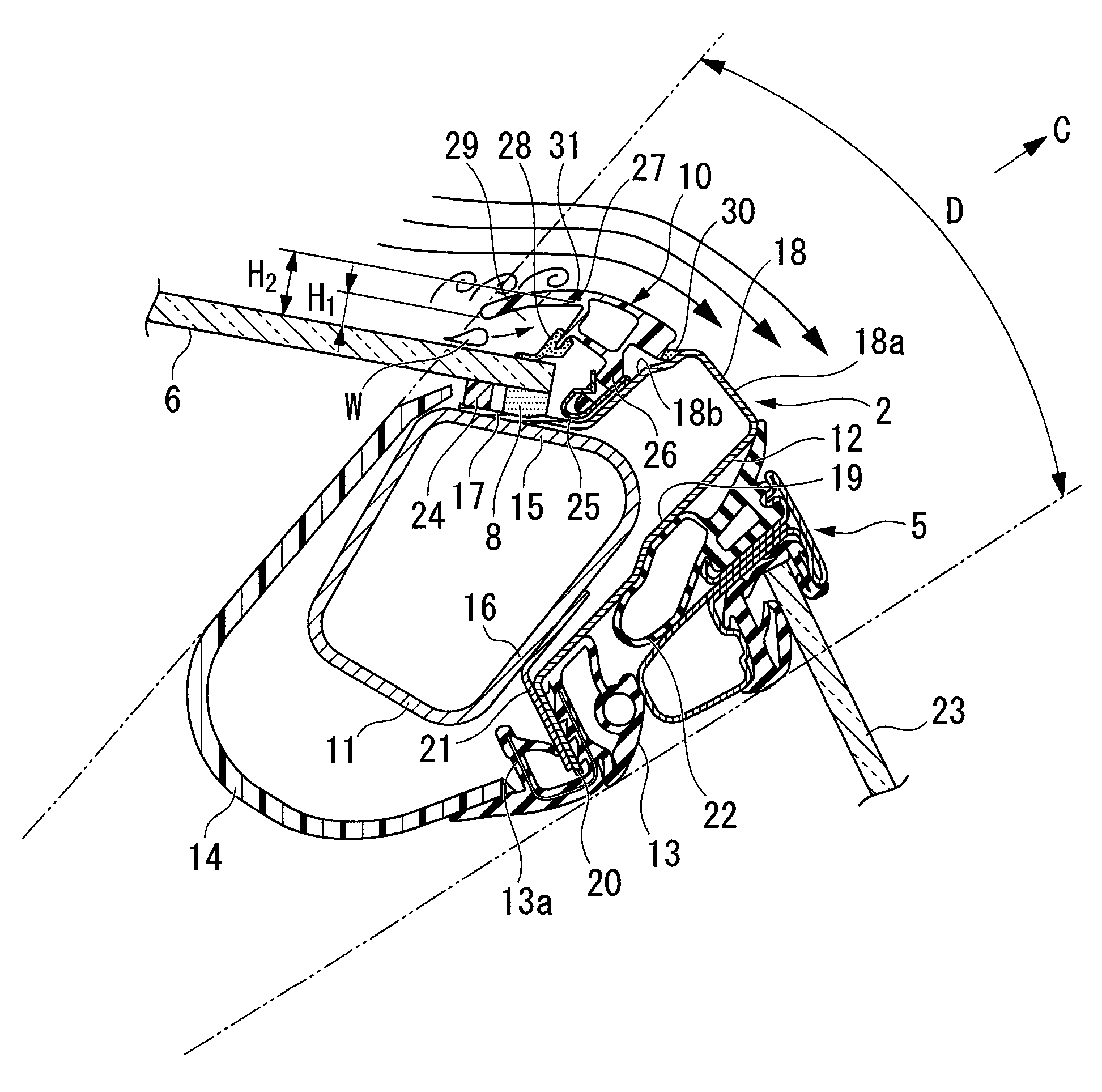
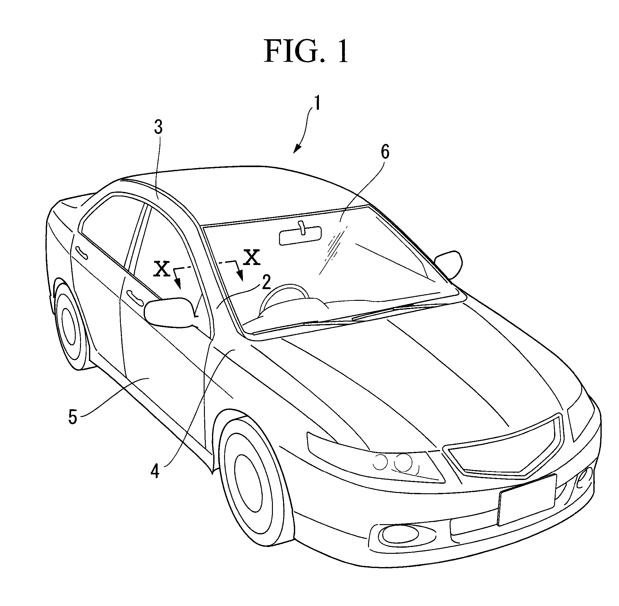
[0033]In the present embodiment, a drip molding 10 for a vehicle 1, in accordance with the present invention, is installed between a front pillar 2 and a front windowpane 6 (see FIG. 1).

[0034]As shown in FIG. 1, the front pillar 2 couples a roof side part 3 and a front body side part 4 of the vehicle 1 to each other, and forms part of a side opening of the vehicle body, which is closed or opened using a front door 5. The front pillar 2 also supports a side edge of the front windowpane 6.

[0035]As shown in the sectional view of FIG. 2, the front pillar 2 has a hollow member 11 made of metal; an outer panel 12 made of metal, attached to a side of the hollow member 11 toward the ou...


PUM


Abstract

A drip molding supported by a pillar at a corner of the front or back of a vehicle, for draining waterdrops entering a side edge of a front or back windowpane. The drip molding has a base attached to the pillar; a part for sealing a gap between the base and the side edge; and a lip part extending from the base to the front surface of the windowpane to form a drainage path between the lip part and the windowpane. On the outside of the lip part, a bent surface is arranged so as to form an arc bending toward the front surface of the windowpane, and an inner face of the lip part is formed in a manner such that the larger a distance from the head toward the root of this part, the larger the distance between this inner face and the front surface of the windowpane.

Description

BACKGROUND OF THE INVENTION[0001]1. Field of the Invention[0002]The present invention relates to a drip molding for a vehicle, which is used for draining waterdrops which enter a side edge of a windowpane on the front or back side of the vehicle.[0003]Priority is claimed on Japanese Patent Application No. 2005-305447, filed Oct. 20, 2005, the content of which is incorporated herein by reference.[0004]2. Description of the Related Art[0005]Generally, a drip molding having a function of draining raindrops or the like is arranged at a side edge of a front windowpane of a vehicle. The drip molding has an attachment base which is attached to a front pillar, and from the attachment base, a glass pane (i.e., windowpane) sealing part and a furnishing lip part extend. The glass pane sealing part is disposed so as to be in close contact with the front surface of a side edge of the front windowpane, and the furnishing lip part projects toward the front surface of the front windowpane 6 so as t...

Claims


Application Information

Patent Timeline
Patent Type & Authority Patents(United States)
IPC IPC(8): B62D25/00B60J1/02
CPCB60J10/0045B60J10/02B60J10/25B60J10/70
Inventor YOSHIOKA, JUNICHIWATARAI, MASAYUKIHAMADA, SHUHEI
Owner HONDA MOTOR CO LTD
Learn More