
Leadframe and packaged light emitting diode

a light-emitting diode and led-type technology, applied in the field of led-type devices, can solve the problems of loss of photometric efficiency, increased junction temperature of leds, and structural instability of prior led packages, and achieve the effect of high luminous power

Active Publication Date: 2008-04-22
SEOUL SEMICONDUCTOR
View PDF9 Cites 64 Cited by
  • Summary
  • Abstract
  • Description
  • Claims
  • Application Information

AI Technical Summary

Benefits of technology

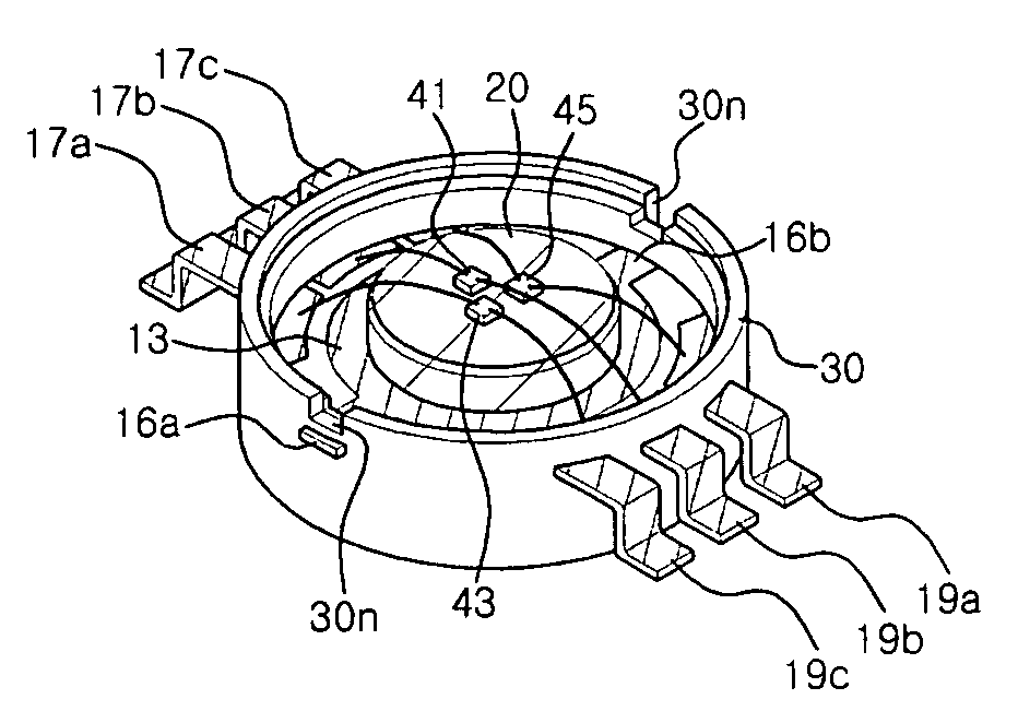
[0006]An embodiment of the present invention relates to providing an LED package capable of preventing the increase of junction temperature of an LED die under high input power, thereby obtaining high luminous power, and a method of fabricating the same.
[0007]Another embodiment of the present invention relates to providing an LED package capable of preventing a heat sink from being separated from a package body, and a method of fabricating the same.
[0008]Yet another embodiment of the present invention relates to providing a leadframe suitable for easily fabricating a structurally stable LED package with good heat dissipation characteristics.

Problems solved by technology

However, the increase of the input power results in the increase of the junction temperature of the LED.
The increase of the junction temperature of the LED causes the loss of photometric efficiency which represents the conversion rate of input energy into visible light.
However, the prior LED package is not structurally stable, since the heat sink can be easily separated from the package body.
When the heat sink is separated from the package body, bonding wires electrically connecting the leads and the LED die mounted on an upper portion of the heat sink are cut off to bring an irreparable damage to the LED package.

Method used


Image

  • Leadframe and packaged light emitting diode
  • Leadframe and packaged light emitting diode
  • Leadframe and packaged light emitting diode

Examples


Embodiment Construction

[0035]Reference will now be made in detail to preferred embodiments of the present invention, examples of which are illustrated in the accompanying drawings.

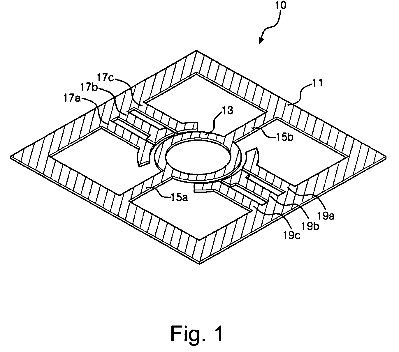
[0036]FIG. 1 is a perspective view of a leadframe according to one embodiment of the present invention.

[0037]Referring to FIG. 1, a leadframe 10 includes a heat sink supporting ring 13 into which a heat sink can be inserted. The supporting ring 13 may be formed in a circular ring shape as shown in FIG. 1, which is not limited thereto, but may be formed in a polygonal ring shape.

[0038]The supporting ring 13 is enclosed by an outer frame 11. The outer frame 11 is spaced apart from the supporting ring 13. The outer frame 11 may be formed in a square shape as shown in FIG. 1, which is not limited thereto, but may be formed in a circular shape or polygonal shape.

[0039]The outer frame 11 and the supporting ring 13 are connected to each other via at least one supporting lead 15a and / or 15b. The supporting ring 13 is fixed to the outer ...


PUM


Abstract

A leadframe that is configured to be used with an electronic device, e.g., light emitting diode (LED), includes a heat sink supporting ring for supporting a heat sink. An outer frame is spaced apart from the heat sink supporting ring, and encloses the heat sink supporting ring. At least one supporting lead connects the heat sink supporting ring and the outer frame. A separated lead is extended from the outer frame toward the heat sink supporting ring, and is spaced apart from the heat sink supporting ring. A package body that may be formed by an injection molding after a heat sink is inserted into the leadframe.

Description

CROSS-REFERENCES TO RELATED APPLICATIONS[0001]The present application claims priority to Korean Patent Application No. 10-2004-0106936, filed Dec. 16, 2004, Korean Patent Application No. 10-2004-0113722, filed Dec. 28, 2004, Korean Patent Application No. 10-2005-0000269, filed Jan. 3, 2005, which are incorporated by reference.BACKGROUND OF THE INVENTION[0002]The present invention relates to a leadframe, a method of fabricating a light emitting diode package using the leadframe, and the light emitting diode package fabricated by the method, and more particularly to a leadframe having a heat sink support ring capable of fixing a heat sink to a leadframe to prevent the heat sink from being separated from a package body, a method of fabricating a light emitting diode package using the leadframe, and the light emitting diode package fabricated by the method.[0003]The luminous power of the light emitting diode (hereinafter referred to as LED) is substantially proportional to the input pow...

Claims


Application Information

Patent Timeline
Patent Type & Authority Patents(United States)
IPC IPC(8): H01L33/00H01L33/50H01L33/54H01L33/56H01L33/62H01L33/64
CPCH01L23/4334H01L33/62H01L25/0753H01L33/642H01L33/647H01L2224/48091H01L2924/01079H01L2924/00014H01L24/48H01L2924/12041H01L2924/181H01L2224/45099H01L2224/45015H01L2924/207H01L2924/00
Inventor KIM, DO HYUNGLEE, CHUNG HOONLEE, KEON YOUNG
Owner SEOUL SEMICONDUCTOR
Learn More