Systems and methods for fatigue testing stents

a technology of system and method, applied in the field of systems, can solve the problems of cumbersome number of cycles required to render such arrangements reliable, small cyclic load, etc., and achieve the effects of easy monitoring and identification, increased resistance, and short tim

Inactive Publication Date: 2008-04-29
CORDIS CORP
View PDF10 Cites 21 Cited by
  • Summary
  • Abstract
  • Description
  • Claims
  • Application Information

AI Technical Summary

Benefits of technology

[0008]Each station further comprises an adjuster and a retainer secured thereto. Each adjuster further comprises a threaded hub to which a respective retainer is secured. The retainer thus helps secure the expander relative to the adjuster. Guide pins are provided on one of the upper plate or lower plate in order to help align the expansion pins with the corresponding expanders when the upper plate and the lower plate are closed toward one another for testing.
[0009]A respective one of the one or more stents is arranged over a corresponding expander for testing thereof. Each stent is provided with wire leads connecting the respective stent to an ohmmeter. Electrical resistance of each stent is thereafter monitored by the ohmmeter as cyclic strains are imparted to the respective one or more stents by insertion of the respective expansion pins into the corresponding expanders occurs. Relatively large cyclic strains are imparted to the stents, as compared to conventional fatigue testers using internal pressurization of tubing into which a stent has been deployed. When the number of strain cycles exceeds the fatigue limit of the stent, resulting in fracture or other architectural failure of the stent, a change in resistance is identified by the ohmmeter. An increase in resistance typically identifies a failure or other compromise in the one or more struts. The onset of fatigue or failure is more readily monitored and identified than in conventional fatigue testers. Furthermore, the ability to impose relatively larger cyclic strains enables an accelerated fatigue test in which the same mode of failure can be achieved in fewer cycles, and therefore in shorter time. Stents of different designs, materials, or structural configurations are more readily compared according to the systems and methods described herein, as well.

Problems solved by technology

The number of cycles required for to render such arrangements reliable can prove cumbersome, however.
Moreover, in fatigue testers where the specimen is positioned within a flexible tubing during testing, cyclic loading tends to be small.

Method used


Image

  • Systems and methods for fatigue testing stents
  • Systems and methods for fatigue testing stents
  • Systems and methods for fatigue testing stents

Examples


Embodiment Construction

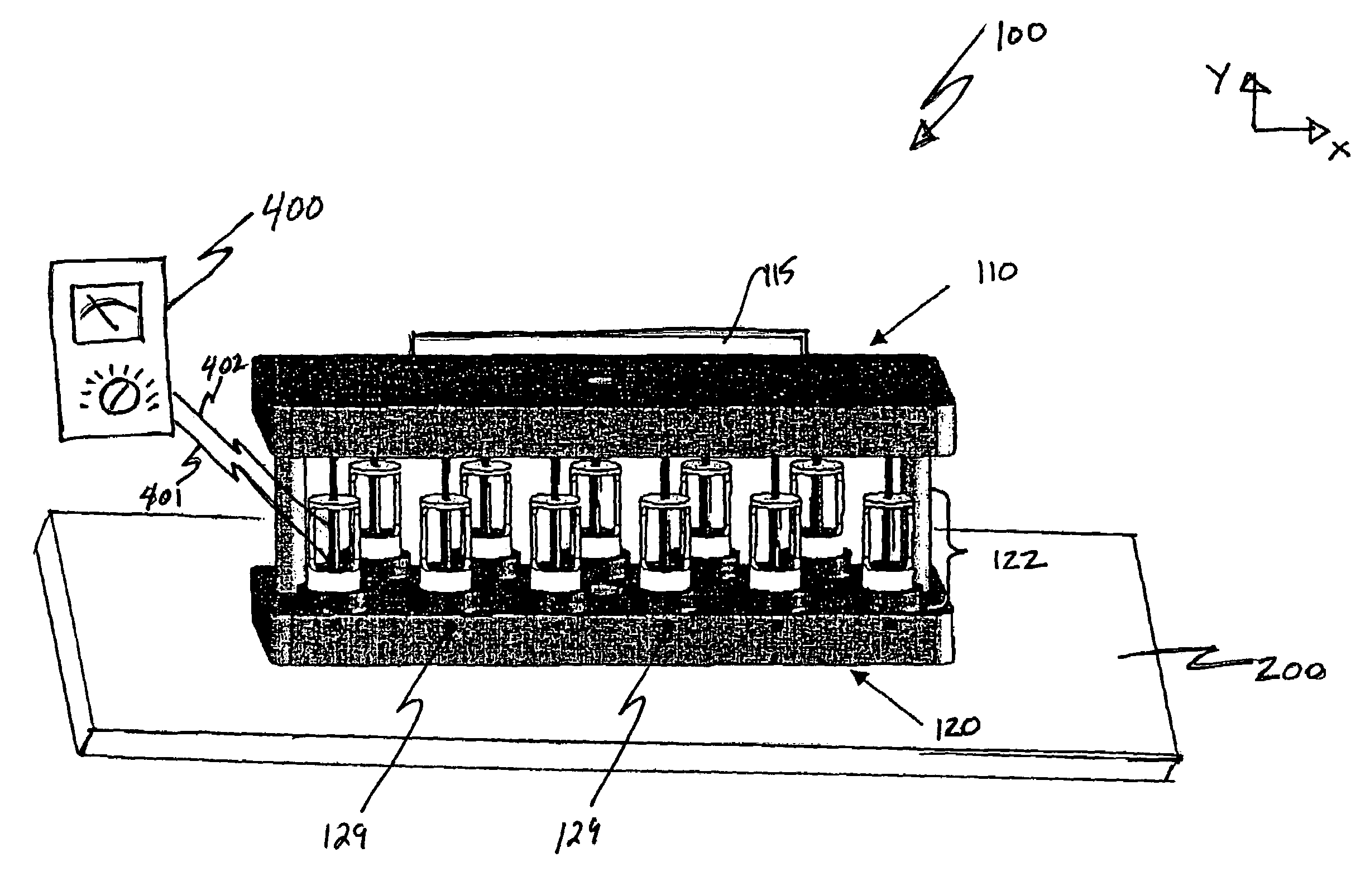
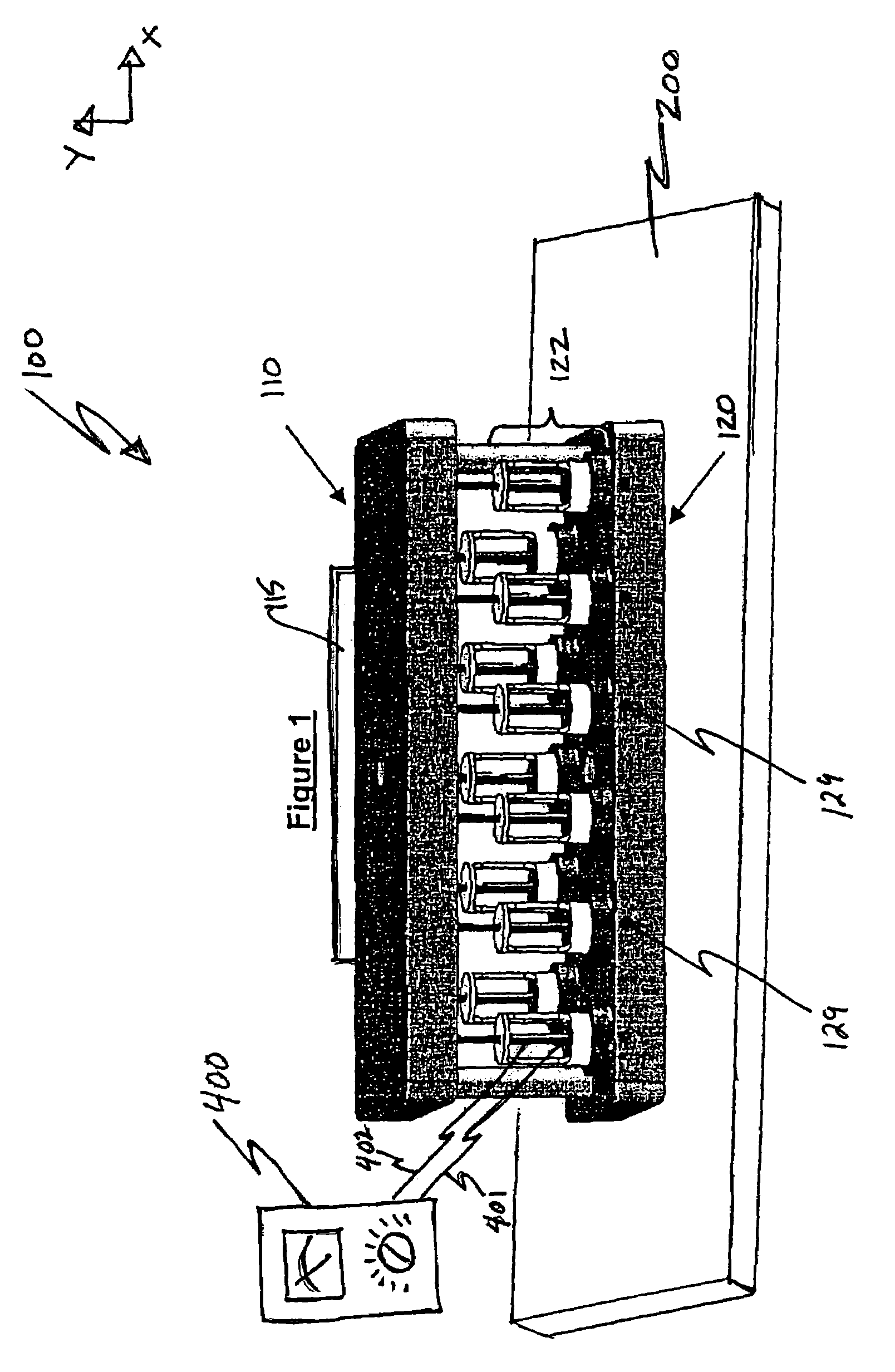
[0019]FIG. 1 illustrates schematically an embodiment of a stent fatigue tester 100 according to the systems and methods of the invention. The stent fatigue tester 100 comprises an upper plate 110 and a lower plate 120. As shown in FIG. 1, the lower plate 120 is fixedly connected to a table top 200, a load cell or other structure, for example, and the upper plate 110 is movable relative to the fixed lower plate 120. The upper plate 110 may be attached to a crosshead 115, or other structure, to accommodate the movement thereof the upper plate. Of course, although not shown, the artisan will readily appreciate that the inverse is also achievable within the context of the fatigue tester 100 described herein such that the upper plate 110 is fixed and the lower plate 120 is movable relative thereto. In any event, the movable plate is movable in the X and Y directions in order to better align the fixed plate with one another in operation. Although omitted from subsequent views, the table t...


PUM

PropertyMeasurementUnit
electrical resistanceaaaaaaaaaa
compressive deformationaaaaaaaaaa
resistanceaaaaaaaaaa

Abstract

Systems and methods for fatigue testing one or more stents based on measured electrical resistance levels of each stent. Pairs of lead lines from an ohmmeter are connected to a respective stent. The respective stent is mounted onto an expander having an interior tapered portion into which a correspondingly tapered expansion pin is received. Cyclic loading strains are applied to the respective stent as an expansion pin is inserted into a corresponding one of the expanders. Stent fracture or failure occurs when cyclic loading exceeds the stents architectural and material capacity. Such fracture fatigue or failure is identified by increased electrical resistance levels. Resistance may be continuously monitored to more readily identify the onset of fatigue or failure. The expansion pins extend from a movable plate, and the expanders comprise a part of corresponding stations that extend from a fixed plate.

Description

BACKGROUND OF THE INVENTION[0001]1. Field of the Invention[0002]The invention generally relates to systems and methods for fatigue testing one or more stents. More specifically, the invention relates to systems and methods for determining fatigue levels of one or more stents based on electrical resistance data associated with the one or more stents.[0003]2. Related Art[0004]Modern medical procedures routinely employ implants placed in a patient's vascular system to perform various therapeutic functions. As an example, stents are often inserted in an artery of a patient to maintain a flow lumen through the artery at a location that had previously been at least partially blocked. Ideally such stents, or other vascular prostheses, are able to withstand the physiological dynamics that occur within the vessel or organ in which they are emplaced. Where fracture, or other failure, of the stent, or other prosthesis, occurs removal and replacement thereof is typically necessitated. Providing...

Claims


Application Information

Patent Timeline
Patent Type & Authority Patents(United States)
IPC IPC(8): G01N3/32A61F2/82G01M99/00
CPCG01N3/32A61F2/82G01N2203/0005G01N2203/0073G01N2203/0266
Inventor BLACK, ERINBURGERMEISTER, ROBERTGRISHABER, RANDY-DAVID BURCEOVERAKER, DAVID W.
Owner CORDIS CORP
Why Eureka
Try Eureka