Heat sink

a technology of heat sink and heat sink body, which is applied in the direction of cooling/ventilation/heating modification, semiconductor/solid-state device details, microprocessors or chipsets, etc., can solve the problems of reducing product reliability, failure of heat generating components, and large amount of heat generated by heat generating components in computers such as central processing units, so as to improve product reliability, reduce heat stress efficiently, and increase the deformable length of the base

Active Publication Date: 2008-04-29
INVENTEC CORP
View PDF6 Cites 8 Cited by
  • Summary
  • Abstract
  • Description
  • Claims
  • Application Information

AI Technical Summary

Benefits of technology

[0007]According to the above defects, an objective of the present invention is to provide a heat sink which can efficiently decrease the heat stress.
[0008]Another objective of the present invention is to provide a heat sink which can increase reliability of products.
[0011]Compared with the prior art, the deformable portions disposed on the base of the heat sink can increase the deformable length of the base such that the heat stress can be efficiently decreased, thereby avoiding such problems as cracks of the soldering portions and deformations of the printed circuit board in the prior art and accordingly increasing product reliability.

Problems solved by technology

It is well known that heat generating components in a computer such as central processing units, microprocessors or chipsets generate a large amount of heat during the computer operates.
As the generated heat increases above a critical temperature, a failure can occur in the heat generating components.
However, since the heat sink is made of different materials with different coefficients of thermal expansion, the heat stress is introduced which can cause such problems as cracks of the soldering portions 40 and deformations of the printed circuit board 50, thereby decreasing reliability of products.

Method used


Image

  • Heat sink
  • Heat sink
  • Heat sink

Examples


Embodiment Construction

[0017]Hereunder, embodiments of the present invention will be described in full detail with reference to the accompanying drawings.

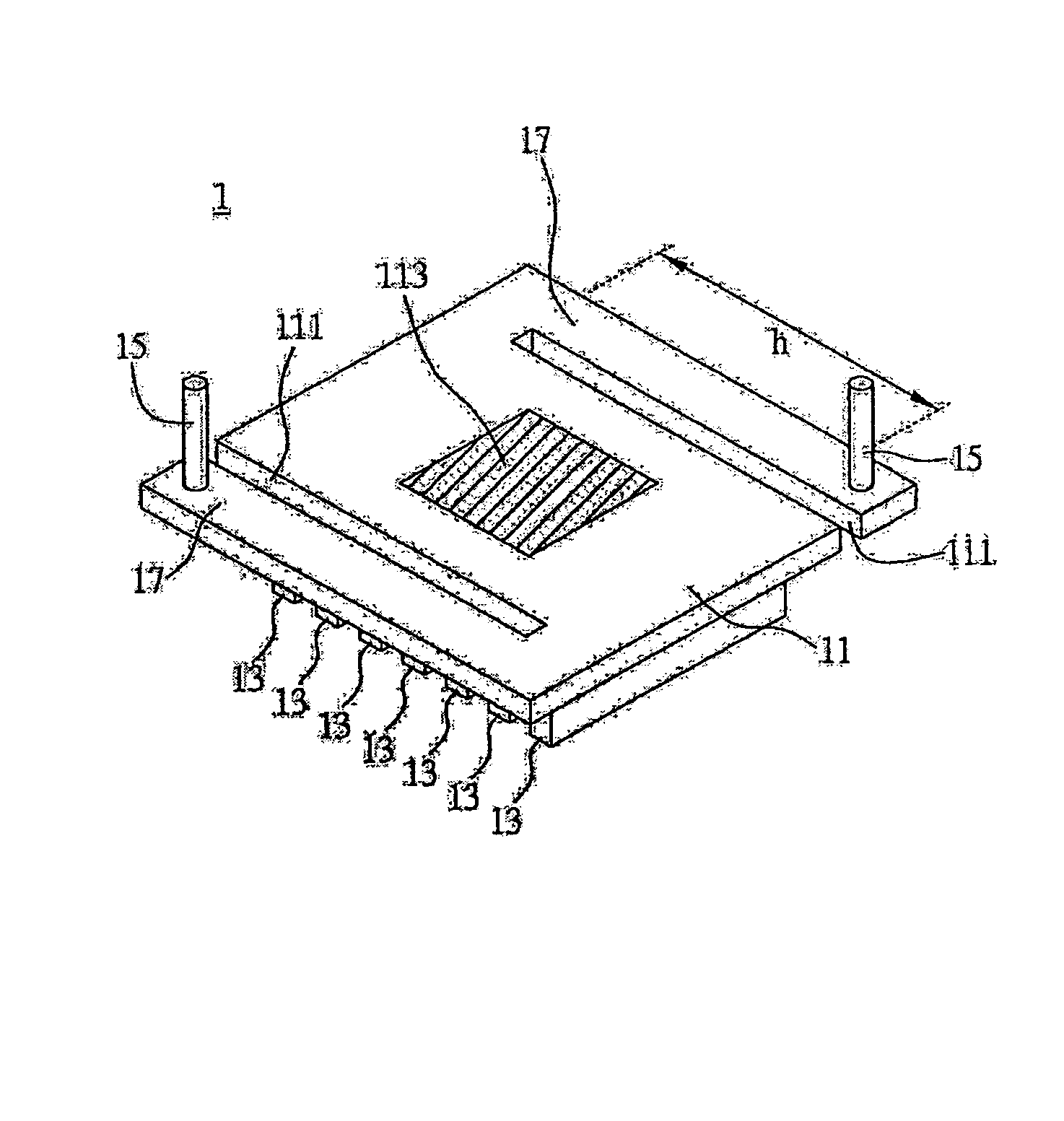
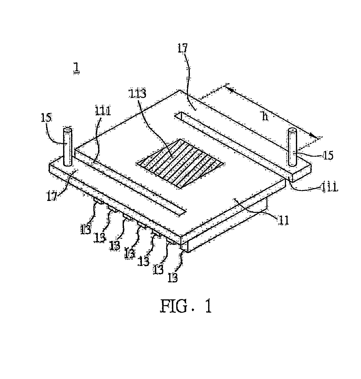
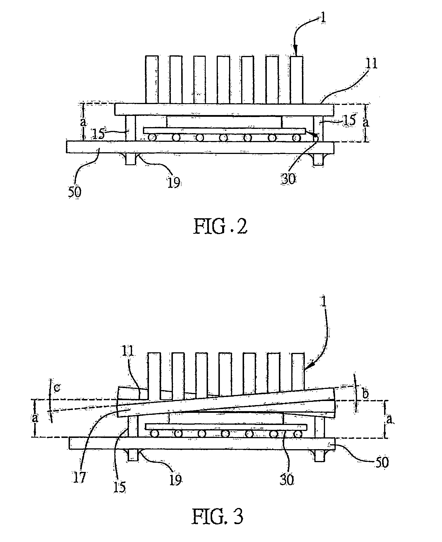
[0018]FIGS. 1 to 3 are diagrams of the heat sink according to a preferred embodiment of the present invention. The heat sink of the present invention can be directly attached to a heat generating component, such as a chipset, a central processing unit, a micro processing unit and so on. In the present embodiment, the heat generating component is a chipset.

[0019]Referring to FIG. 1, the heat sink 1 comprises a base 1, a set of fins 13 attached to a surface of the base 11 and a plurality of fixing portion 15 extending from the opposite surface of the base 1. The heat sink 1 is improved by forming a plurality of slots 111 at lateral sides of the base 11 such that a plurality of deformable portions 17 can be defined on the base 11 so as to increase the deformable length of the base 11, thereby relaxing the heat stress.

[0020]The base 11 is a substantially rec...


PUM


Abstract

A heat sink includes a base, a set of fins mounted to the base and a plurality of fixing portions, wherein the fixing portions extend from a surface of the base and the set of fins are mounted on an opposite surface of the base. The heat sink is secured to a printed circuit board with at least one heat generating component through the fixing portion of the base. The heat sink is improved by forming one or more slots at lateral sides of the base such that one or more deformable portions can be defined on the base. Thus, the deformable length of the base is increased and the heat stress is relaxed.

Description

FIELD OF THE INVENTION[0001]The present invention relates to a heat sink, and more particularly, to a heat sink for dissipating heat generated from a heat generating component which is in contact with the heat sink.BACKGROUND OF THE INVENTION[0002]It is well known that heat generating components in a computer such as central processing units, microprocessors or chipsets generate a large amount of heat during the computer operates. As the generated heat increases above a critical temperature, a failure can occur in the heat generating components. Therefore, the excess heat must be dissipated to prevent such failures.[0003]Since a chipset is responsible for data transferring between primary chips and peripheral I / O components, it is particularly important to dissipate heat generated by the chipset. Usually, the chipset is in close contact with a heat sink for efficient heat dissipation. Such a heat sink is shown in FIG. 4 and FIG. 5.[0004]As shown in FIG. 4, the heat sink includes a b...

Claims


Application Information

Patent Timeline
Patent Type & Authority Patents(United States)
IPC IPC(8): F28F7/00
CPCH01L23/367H01L2023/4081H01L2924/0002H01L2924/00
Inventor LIN, SHU-JULIU, LI-TAI
Owner INVENTEC CORP
Why Eureka
Try Eureka