Hybrid glass-sealed electrical connectors
a technology of electrical connectors and glass seals, applied in the direction of coupling device connections, wellbore/well accessories, survey, etc., can solve the problems of increasing hostile environment for these connectors, corroding the environment of natural or chemically enhanced wellbores, and certain disadvantages and limitations of both types of connectors
- Summary
- Abstract
- Description
- Claims
- Application Information
AI Technical Summary
Benefits of technology
Problems solved by technology
Method used
Image
Examples
second embodiment
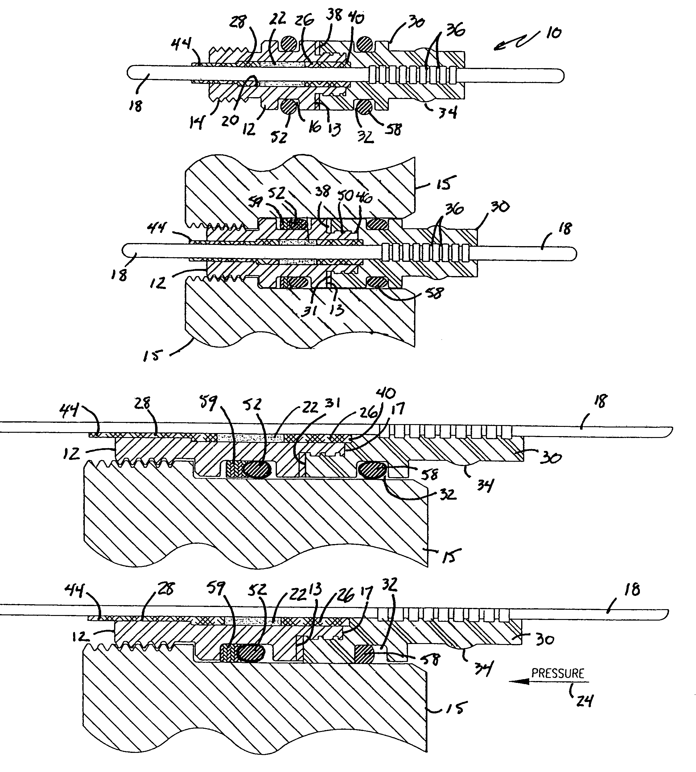
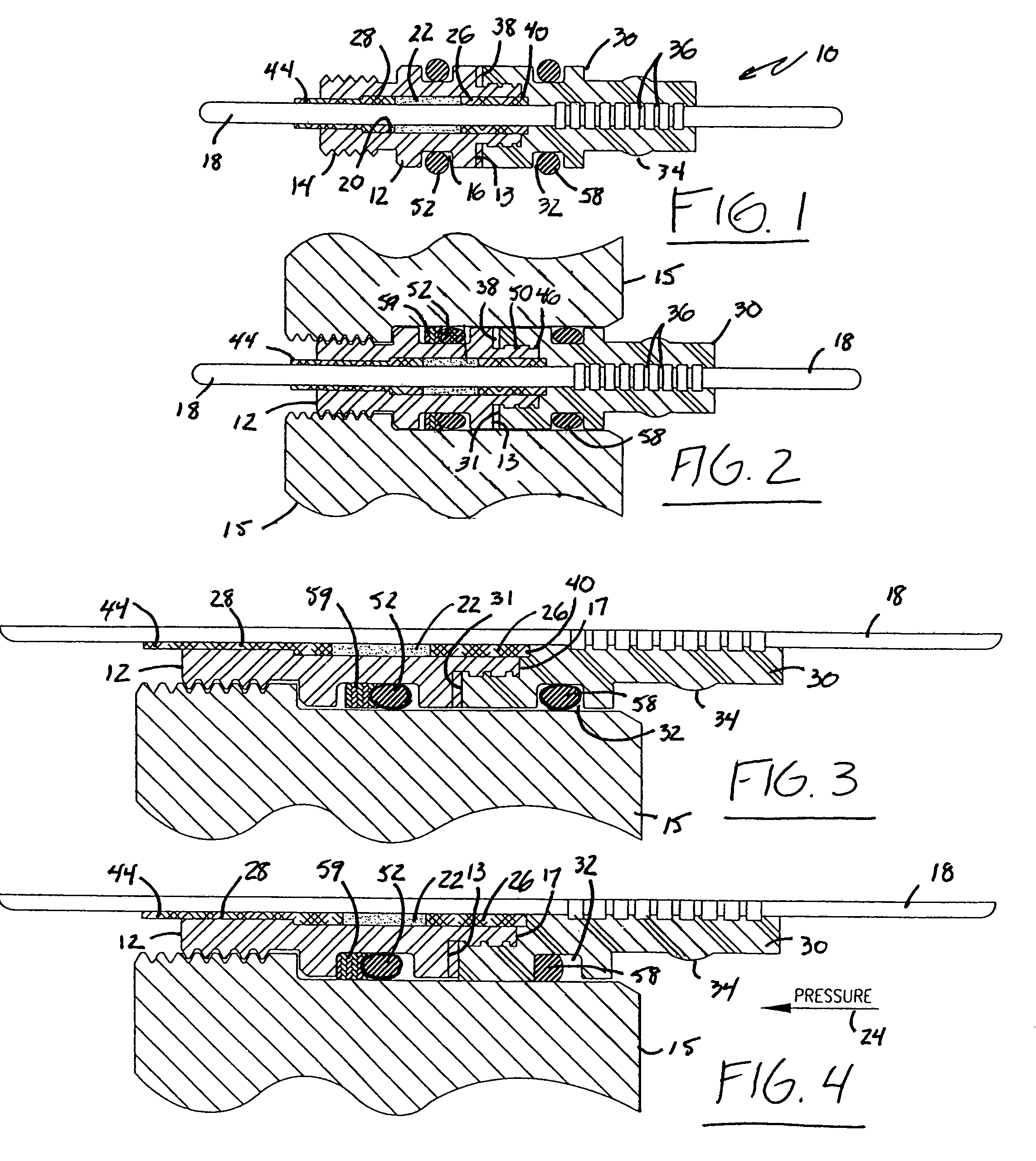
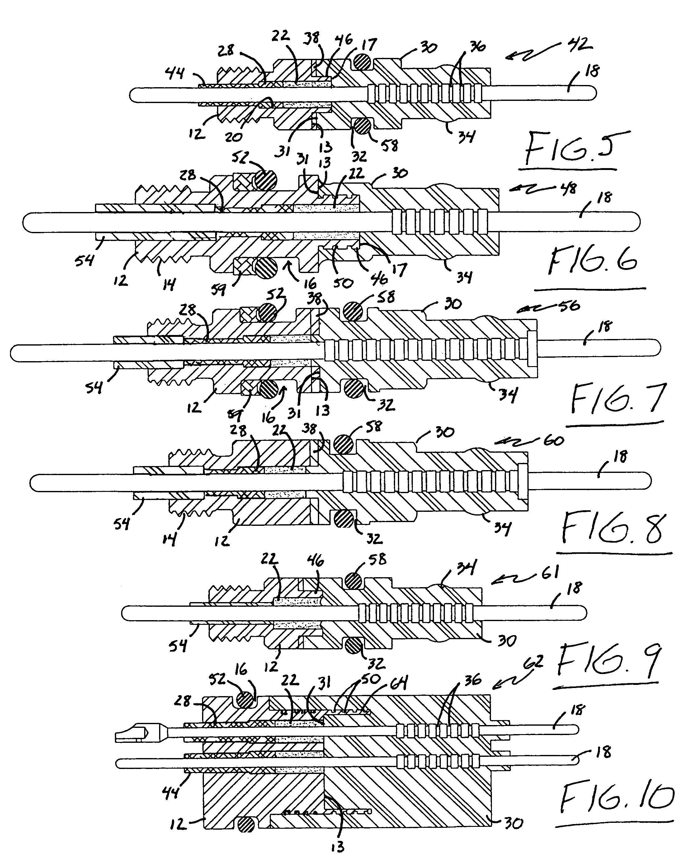
[0047]Referring now to FIG. 5, a connector constructed in accordance with the present invention is indicated generally at reference numeral 42. Connector 42 is comprised of the same component parts as connector 10 shown in FIG. 1 such that the same reference numerals are used to designate the common parts of both embodiments, but connector 42 is intended for use in different applications than the connector 10 shown in FIGS. 1-4 in that the metal body 12 of connector 42 lacks a groove such as the groove 16 in the body 12 of connector 10 (FIGS. 1-4) for an O-ring for effecting the above-described seal with the bulkhead (not shown) of the electrical apparatus to which the body 12 is engaged. Another difference between connector 42 and connector 10 can be seen by reference to the annulus between the O.D. of conductor 18 and the I.D. of the bore 20 through metal body 12. Instead of rings of ceramic material on both the high and low pressure sides of the glass seal 22 such as the ceramic ...
third embodiment
[0048]the connector of the present invention is shown at reference numeral 48 in FIG. 6. In the connector 48, the O.D. of nipple 46 is provided with a plurality of grooves 50 such that, when jacket 30 is overmolded onto body 12, the connection is even more secure than in the connector 42 shown in FIG. 5. By comparison of the connector 48 in FIG. 6 to the connectors 10 and 42 in FIGS. 1-5, it can be seen that no groove is provided for an O-ring on the O.D. of jacket 30 such that the connector 48 seals only to the bulkhead (not shown) of the electrical apparatus to which the metal body 12 is threadably engaged. An O-ring 52 and back-up ring 59 are shown in the groove 16 for that purpose. It can also be seen that the connector 48 is provided with an insulating, flexible sleeve 54 on the low pressure side of the ceramic insulator 28 to provide some flexibility and / or vibration resistance to the connector 48 and to decrease the likelihood of damage to the ceramic insulator 28 from bendin...
fourth embodiment
[0049]a connector constructed in accordance with the present invention is indicated generally at reference 56 in FIG. 7. Both the O-ring 52 in groove 16 and the O-ring 58 in groove 32 for effecting independent primary and secondary seals are shown in FIG. 7. Those skilled in the art who have the benefit of this disclosure will recognize that, although not required in all applications, it may be advantageous to provide back-up rings 59 for better effecting the seal between the O.D. of connector 56 and the bulkhead of the electrical apparatus to which connector 56 is engaged.
PUM
 Abstract
Description
Claims
Application Information
 - R&D
- Intellectual Property
- Life Sciences
- Materials
- Tech Scout
- Unparalleled Data Quality
- Higher Quality Content
- 60% Fewer Hallucinations
Browse by: Latest US Patents, China's latest patents, Technical Efficacy Thesaurus, Application Domain, Technology Topic, Popular Technical Reports.
© 2025 PatSnap. All rights reserved.Legal|Privacy policy|Modern Slavery Act Transparency Statement|Sitemap|About US| Contact US: help@patsnap.com


