Radio frequency IC tag and method for manufacturing same

a radio frequency ic tag and radio frequency technology, applied in the direction of instruments, resonant antennas, burglar alarm mechanical actuation, etc., can solve the problems of inability to structure radio frequency ic tags having a length smaller than or equal to /2, and the antenna efficiency is remarkably reduced, so as to achieve sufficient communication distance, sufficient communication distance, and the effect of extending the communication distan

Inactive Publication Date: 2008-04-29
HITACHI LTD
View PDF7 Cites 36 Cited by
  • Summary
  • Abstract
  • Description
  • Claims
  • Application Information

AI Technical Summary

Benefits of technology

[0001]The present invention relates to a radio frequency IC tag and a method for manufacturing same and more particularly to a radio frequency IC tag having improved structure of an antenna part provided therein and its manufacturing method.
[0002]Recently, radio frequency IC tags are widely used for information management or distribution management of articles and structures. Such radio frequency IC tags each include a small IC chip in which information is recorded and a small antenna for transmitting the information recorded in the IC chip by radio and are attached to articles or embedded in structures to be utilized. When information (information concerning attributes of individual articles or structures) recorded in the IC chip is read, a reader / writer is merely held to the radio frequency IC tag to make it possible to communicate with the radio frequency IC tag and read the information recorded in the IC chip without contact.
[0003]As such a radio frequency IC tag, the technique disclosed in JP-A-2003-298464 (paragraphs 0067 to 0071 and FIG. 6), for example, is known. In such technique, a microstrip antenna (dipole antenna) including a radiation conductive layer (antenna layer) and a ground layer formed on both sides of a dielectric body is held between a dielectric case made of polypropylene having relatively small dielectric loss. Accordingly, since an antenna part containing an IC chip is covered by a case, the radio frequency IC tag has excellent weather-proof and dust-proof characteristics.

Problems solved by technology

Since the efficiency of the antenna is remarkably reduced and communication is difficult when the length is smaller than λ / 2, the radio frequency IC tag having the length smaller than or equal to λ / 2 cannot be structured.

Method used


Image

  • Radio frequency IC tag and method for manufacturing same
  • Radio frequency IC tag and method for manufacturing same
  • Radio frequency IC tag and method for manufacturing same

Examples


first embodiment

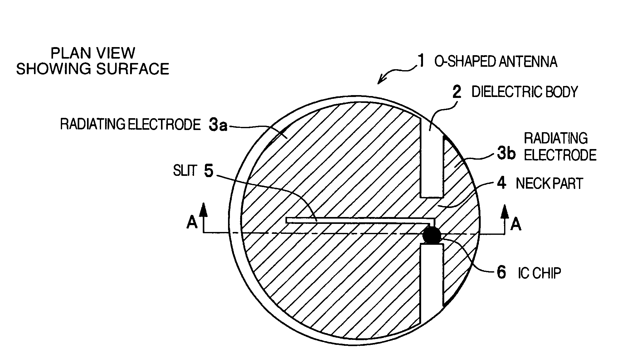
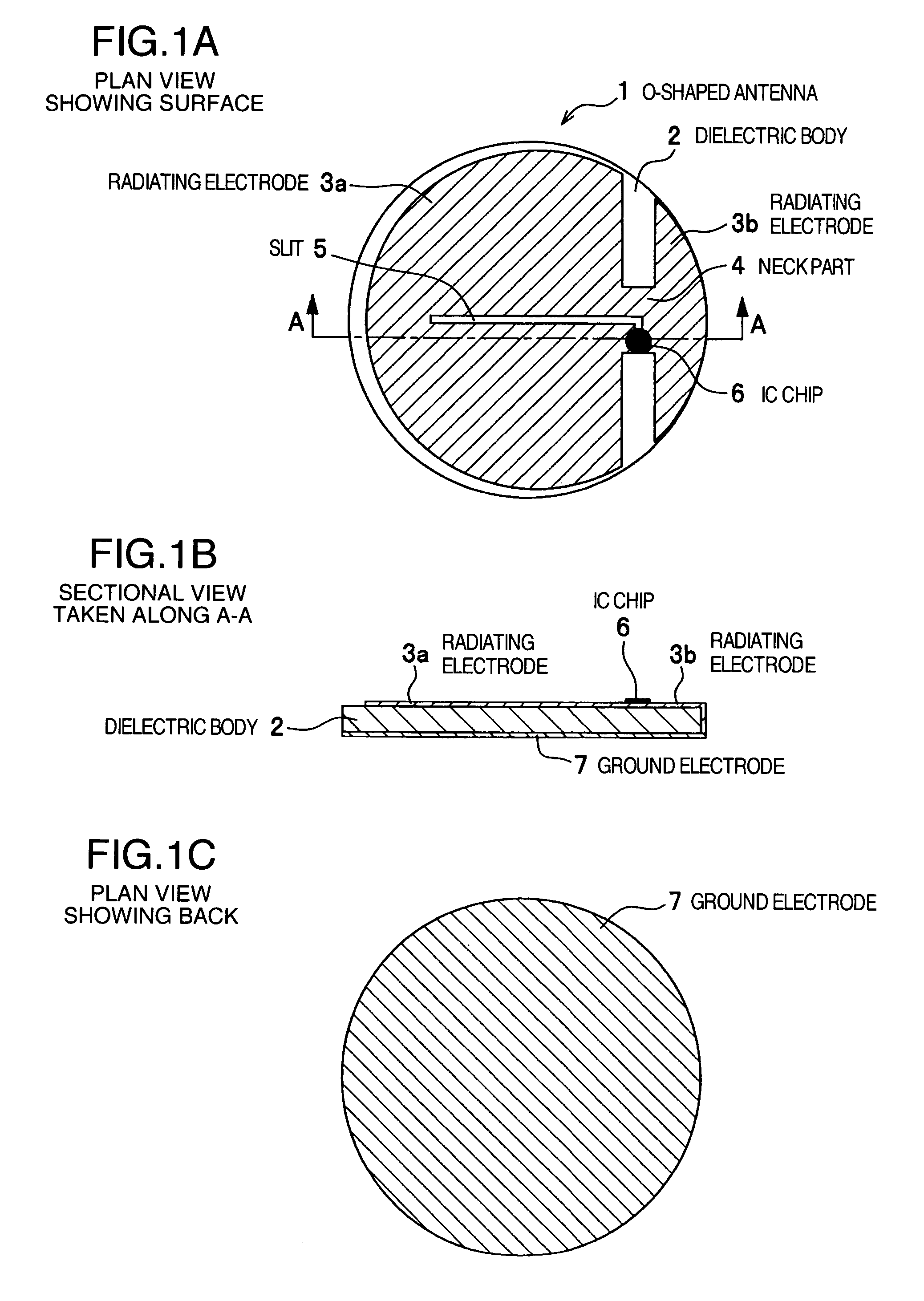
[0035]FIGS. 1A to 1C are diagrams illustrating an O-shaped antenna included in a radio frequency IC tag of the first embodiment according to the present invention. FIG. 1A is a plan view illustrating the surface or the obverse of the O-shaped antenna, FIG. 1B is a sectional view of the O-shaped antenna taken along line A-A in FIG. 1A and FIG. 1C is a plan view illustrating the back or the reverse of the O-shaped antenna. As shown in FIGS. 1A to 1C, the O-shaped antenna 1 (radiating electrode) formed into a circle includes two unsymmetrical semicircular radiating electrodes 3a and 3b formed on the surface of a dielectric body 2 constituting an antenna substrate and an elongated neck part 4 connecting the radiating electrodes 3a and 3b at the middle portion thereof. Further, a slit 5 is formed from the elongated neck part 4 into the radiating electrode 3a. In addition, an IC chip 6 is mounted to straddle the slit 5 in the elongated neck part 4 and respective terminals of the IC chip 6...

second embodiment

[0064]In the second embodiment, manufacturing of the radio frequency IC tag is described.

[0065]FIGS. 7A and 7B are diagrams illustrating the manufacturing process of the radio frequency IC tag of the second embodiment according to the present invention. FIG. 7A illustrates the radio frequency IC tag which is not subjected to forming and FIG. 7B illustrates the radio frequency IC tag which has been subjected to forming. For example, the O-shaped antenna including the unsymmetrical radiating electrodes as shown in FIG. 1A is disposed in the bottom of a previously prepared container as an upper electrode 21 (that is, radiating electrode) as shown in FIG. 7A. The upper electrode 21 is made of copper alloy (for example, phosphor bronze and brass) or ferroalloy having the thickness of 0.1 to 0.3 mm. Further, metal plate material of the upper electrode 21 is subjected to surface processing of terminals such as solder plating, tinning plating, gold plating and palladium plating.

[0066]Next, ...

third embodiment

[0070]In the third embodiment of the present invention, some variations of mass production of radio frequency IC tags by forming a lot of radiating electrodes and ground electrodes in a lead frame are now described.

First Variation

[0071]FIG. 8 is a diagram illustrating the first variation of the third embodiment according to the present invention in which a lot of radiating electrodes and ground electrodes are formed in a lead frame. As shown in FIG. 8, radiating electrodes 32, ground electrodes 33 and slits 34 are formed lengthwise of a beltlike lead frame 31 at equal intervals. The radiating electrodes 32 are formed to have semicircles that are unsymmetrical in the vertical direction and the ground electrodes 33 are formed into a circle. Both the radiating electrodes 32 and the ground electrodes 33 are connected to each other through a short beltlike lead frame 36. Further, feed holes 31a are formed in the lead frame 31 at equal intervals. The lead frame 31 is moved at equal pitch ...


PUM

PropertyMeasurementUnit
frequencyaaaaaaaaaa
depthaaaaaaaaaa
diameteraaaaaaaaaa

Abstract

A small radio frequency IC tag which can obtain sufficiently long communication distance with radio wave in the microwave band even if an antenna is made small and the radio frequency IC tag is embedded in metal material. An O-shaped antenna is formed to narrow the width of a neck part in which an IC chip is mounted and widen the width of radiating electrodes constituting radiating part of radio wave. The radiating electrodes are formed into offset structure on right and left sides of the feeding point so that areas of right and left radiating parts of the feeding point in which the IC chip is mounted are unsymmetrical. Further, a ground electrode is provided so that a dielectric body is held between the radiating electrodes and the ground electrode and the radiating electrode is connected to the ground electrode at the side of the dielectric body.

Description

BACKGROUNG OF THE INVENTION[0001]The present invention relates to a radio frequency IC tag and a method for manufacturing same and more particularly to a radio frequency IC tag having improved structure of an antenna part provided therein and its manufacturing method.[0002]Recently, radio frequency IC tags are widely used for information management or distribution management of articles and structures. Such radio frequency IC tags each include a small IC chip in which information is recorded and a small antenna for transmitting the information recorded in the IC chip by radio and are attached to articles or embedded in structures to be utilized. When information (information concerning attributes of individual articles or structures) recorded in the IC chip is read, a reader / writer is merely held to the radio frequency IC tag to make it possible to communicate with the radio frequency IC tag and read the information recorded in the IC chip without contact.[0003]As such a radio frequ...

Claims


Application Information

Patent Timeline
Patent Type & Authority Patents(United States)
IPC IPC(8): H01Q1/38
CPCH01Q1/22H01Q9/285Y10T29/49018Y10T29/49169Y10T29/49002Y10T29/49146Y10T29/49016Y10T29/49121G06K19/077G06K19/07
Inventor SAKAMA, ISAOASHIZAWA, MINORU
Owner HITACHI LTD
Why Eureka
Try Eureka