Electronic camera and white balance correction circuit

a technology of white balance correction and electronic camera, which is applied in the field of electronic camera and white balance correction circuit, can solve the problems of inability to reproduce images by reproducing images by these methods, unable to gain users' satisfaction, and certain stroboscopic images will be extremely inappropriately reproduced

Inactive Publication Date: 2008-04-29
NIKON CORP
View PDF15 Cites 10 Cited by
  • Summary
  • Abstract
  • Description
  • Claims
  • Application Information

AI Technical Summary

Benefits of technology

[0013]Then, it is an object of the present invention to provide an electronic camera and a white balance correction circuit that use relatively simple processing to properly set white balance correction values at stroboscope imaging (specifically, to set the values more appropriately than by the method (1), by simpler processing than by the foregoing methods (2), (3) and (4)).
[0014]The electronic camera of the present invention has a stroboscope unit or a connection terminal to a stroboscope unit. The electronic camera includes: an imaging unit for capturing an image of a subject; a calculating unit for calculating the color temperature of double illumination according to the image captured with double illumination of field light and strobe light emitted by the stroboscope unit; and a reflection unit for allowing the calculated color temperature to be reflected in a white balance correction value to be applied to the image. When the calculated color temperature is in a predetermined range, the reflection unit decreases the degree of the reflection. Thus, it is possible to set the white balance correction values appropriately at stroboscope imaging by use of relatively simple processing.
[0015]Preferably, the reflection unit allows the white balance correction value to be closer to such a value that suppresses the color of the single illumination of the strobe light when the calculated color temperature is higher than the color temperature of the single illumination. Also preferably, the reflection unit allows the white balance correction value to coincide with such a value that suppresses the color of the single illumination of the strobe light when the calculated color temperature is higher than the color temperature of the single illumination. In this way, a stroboscopic image with distant a background of a low color temperature is reproducible without unnatural reddishness.

Problems solved by technology

According to the method (1), however, the white balance correction is made by use of the same white balance correction values so that a certain stroboscopic image will be extremely inappropriately reproduced.
For example, in a case where strobe light does not sufficiently reach the background of a subject because of a long distance, and besides the color temperature of the illumination to the background is low, an image captured in this condition may have unnaturally reddish background.
According to the methods (2), (3) and (4), they may be adaptable to a variety of stroboscopic images but reproduced images by these methods cannot gain users' satisfaction in spite of the fact that they are complex processing.

Method used


Image

  • Electronic camera and white balance correction circuit
  • Electronic camera and white balance correction circuit
  • Electronic camera and white balance correction circuit

Examples


first embodiment

[0036]A first embodiment of the present invention will now be described with reference to FIGS. 1, 2, 3, 4 and 5. In the present embodiment, a camera system, to which an electronic camera of the invention is applied, will be described below. This electronic camera includes a white balance correction circuit of the invention.

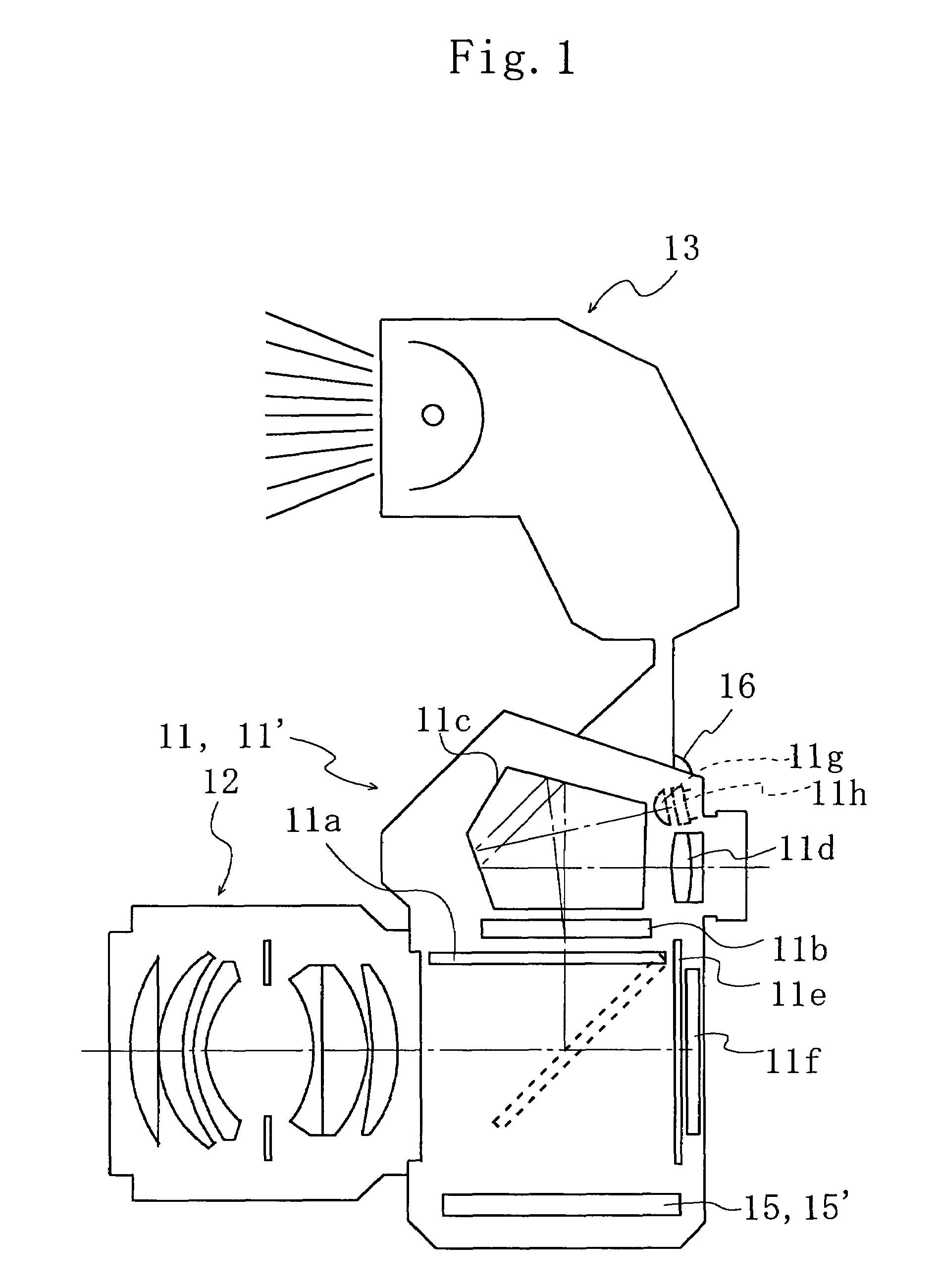
[0037]FIG. 1 is a schematic diagram showing the structure of the camera system of the present embodiment. The camera system includes an electronic camera body 11, a lens 12, and a stroboscope device 13. The lens 12 and stroboscope device 13 may be detachable from the electronic camera body 11. The electronic camera body 11 has operation buttons 16 such as a release button provided thereon with which the operator can change the mode of the electronic camera body 11 between non-stroboscope mode and stroboscope mode or give other imaging instructions to the electronic camera body 11 at his desired timings.

[0038]As illustrated in FIG. 1, the electronic camera body 11...

second embodiment

[0076]A second embodiment of the present invention will now be described with reference to FIGS. 1, 6 and 7. The present embodiment is a modification of the first embodiment. Only the differences in the present embodiment than the first embodiment will be described below.

[0077]As shown in FIG. 1, an electronic camera 11′ of the present embodiment has a condensing lens 11g and a colorimeter 11h. The output of the colorimeter 11h indicates the type of field light (whether the field light is a fluorescent light or not). The electronic camera 11′ of the present embodiment also has a circuit section 15′ in place of the circuit section 15.

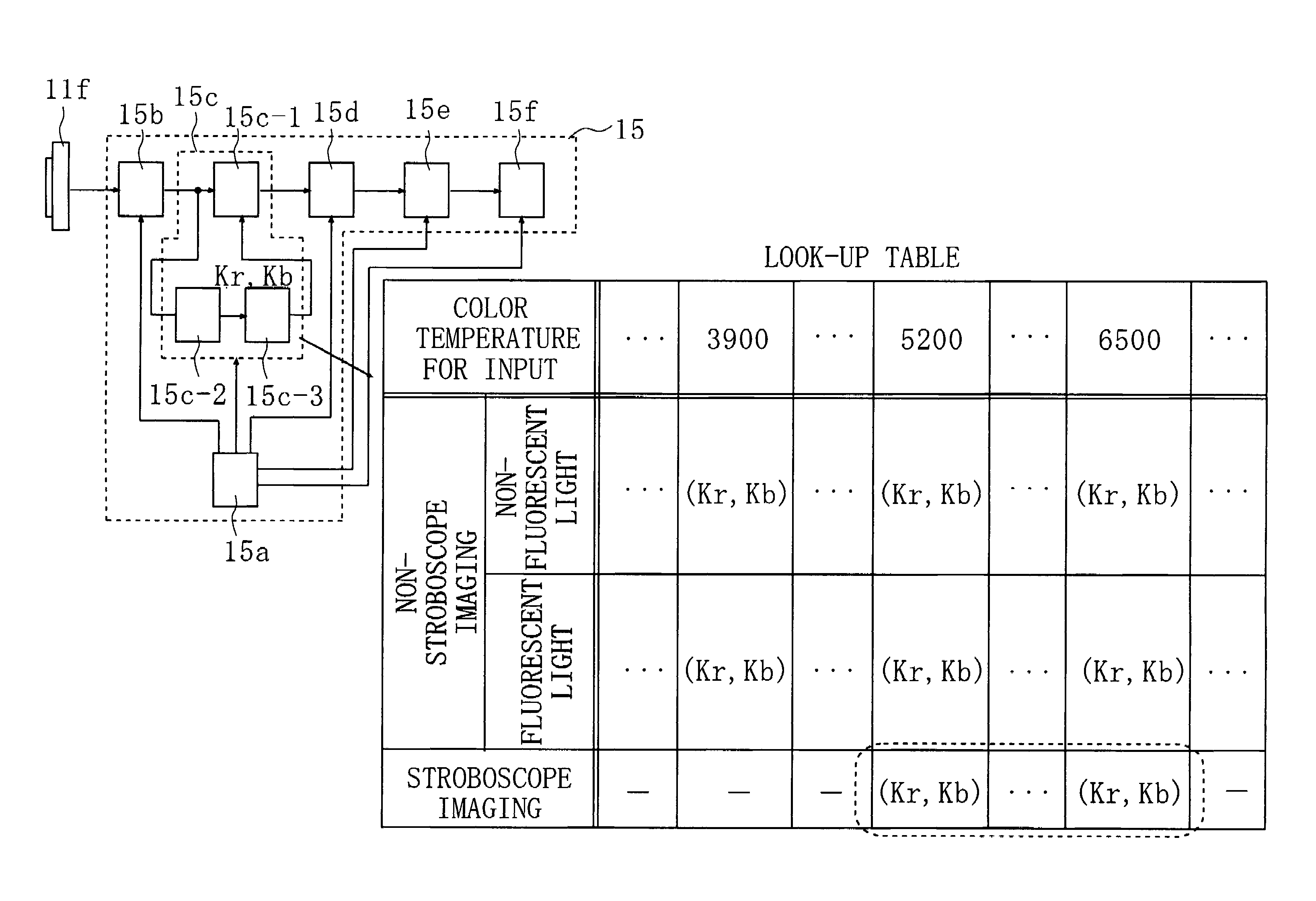
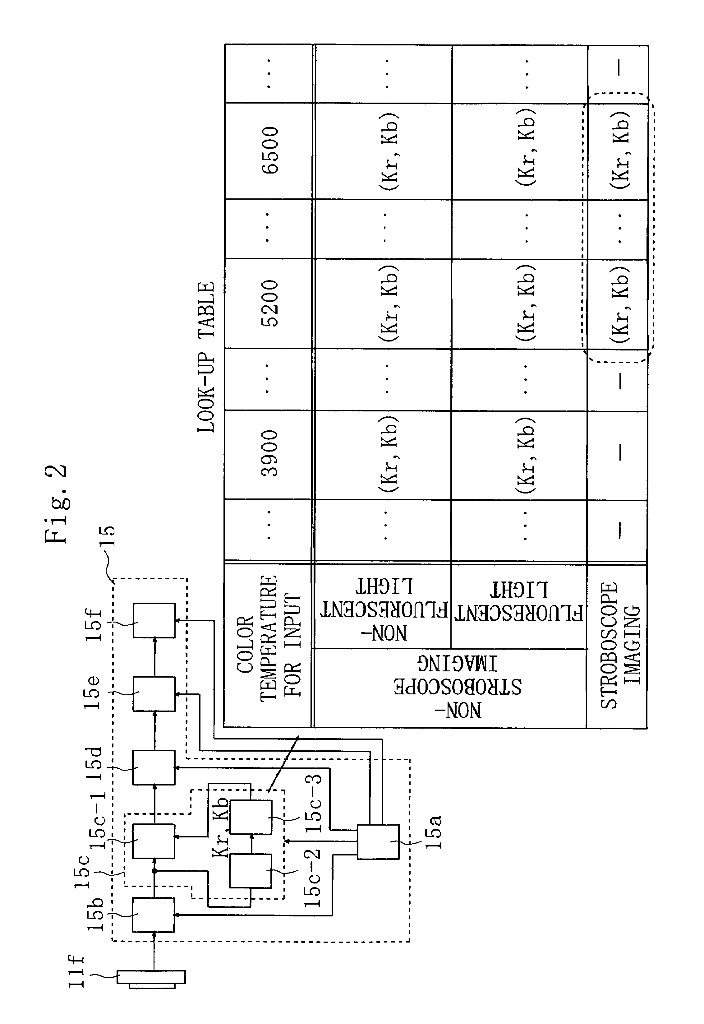
[0078]As shown in FIG. 6, the circuit section 15′ of the present embodiment is the same as the circuit section 15 of the first embodiment except that a CPU 15a′ replaces the CPU 15a of the first embodiment and that a white balance correction circuit 15c′ replaces the white balance correction circuit 15c of the first embodiment. The white balance correcti...


PUM


Abstract

The invention relates to an electronic camera and a white balance correction circuit both capable of setting white balance correction values properly at stroboscope imaging by relatively simple processing. The electronic camera has a stroboscope unit or a connection terminal to a stroboscope unit; an imaging unit for capturing an image of a subject; a calculating unit for calculating, from the image captured with double illumination of both field light and strobe light emitted by the stroboscope unit, the color temperature of the double illumination; and a reflection unit for allowing the calculated color temperature to be reflected in white balance correction values to be applied to the image. When the calculated color temperature is in a predetermined range, the reflection unit decreases the degree of the reflection.

Description

CROSS REFERENCE TO RELATED APPLICATION[0001]This application is based upon and claims the benefit of priority from the prior Japanese Patent Application No. 2002-250104, filed on Aug. 29, 2002, the entire contents of which are incorporated herein by reference.BACKGROUND OF THE INVENTION[0002]1. Field of the Invention[0003]The present invention relates to an electronic camera capable of performing stroboscope imaging and a white balance correction circuit applied to the electronic camera.[0004]2. Description of the Related Art[0005]In general, white balance correction values of an electronic camera are determined according to the color temperature of illumination that illuminates a subject and to the type of the illumination. The color temperature and type of the illumination can be obtained, for example, from an image of the subject and from an output of a colorimeter. The white balance correction values are determined by not only the color temperature of the illumination but also t...

Claims


Application Information

Patent Timeline
Patent Type & Authority Patents(United States)
IPC IPC(8): H04N9/73G03B7/08G03B15/05H04N5/225H04N9/04
CPCH04N5/2256H04N9/735H04N23/56H04N23/88
Inventor TAKESHITA, TETSUYA
Owner NIKON CORP
Why Eureka
Try Eureka