System and method of active latency detection for network applications

a network application and active latency detection technology, applied in the field of network application monitoring, can solve the problems of difficult to identify whether latency is caused by the client system, the network, or the remote server, and difficult to deploy two capture agents,

Active Publication Date: 2008-04-29
DYNATRACE
View PDF11 Cites 45 Cited by
  • Summary
  • Abstract
  • Description
  • Claims
  • Application Information

AI Technical Summary

Benefits of technology

[0010]Systems and methods of active latency detection for network applications are disclosed. Active latency detection allows network latency to be calculated from a single host system. Periodic requests are generated from the host system and directed to a remote system in a way that requires minimal processing by the remote system. For example, the periodic requests may be directed to a port at the remote node that has been identified as closed, causing the request to be denied with minimal processing. The timing information for the requests and responses is stored for use in further processing. Network latencies are calculated from the timing information associated with the periodic requests and can be combined with timing information associated with application packets to generate a latency trace for one or more network applications.

Problems solved by technology

However, identifying whether latency is caused by the client system, the network, or the remote server can be difficult using a single source.
This is particularly problematic because the local node 110 has no direct timing data other than the time at which the application request was generated 130 and processing 140 begins.
The local time delays represent self-queuing delays based upon the backlog of outgoing and incoming packets at the local node and the outgoing and incoming bandwidth.
The network time delays reflect network latency that results from the length of available routes, congestion, failures, intermediate node processing times, and other network delays.
The remote time delay is a black box that includes queuing delays at the remote node, actual application processing time, and other delays.
The negative aspect of this method is that it can be difficult to deploy two capture agents.

Method used


Image

  • System and method of active latency detection for network applications
  • System and method of active latency detection for network applications
  • System and method of active latency detection for network applications

Examples


Embodiment Construction

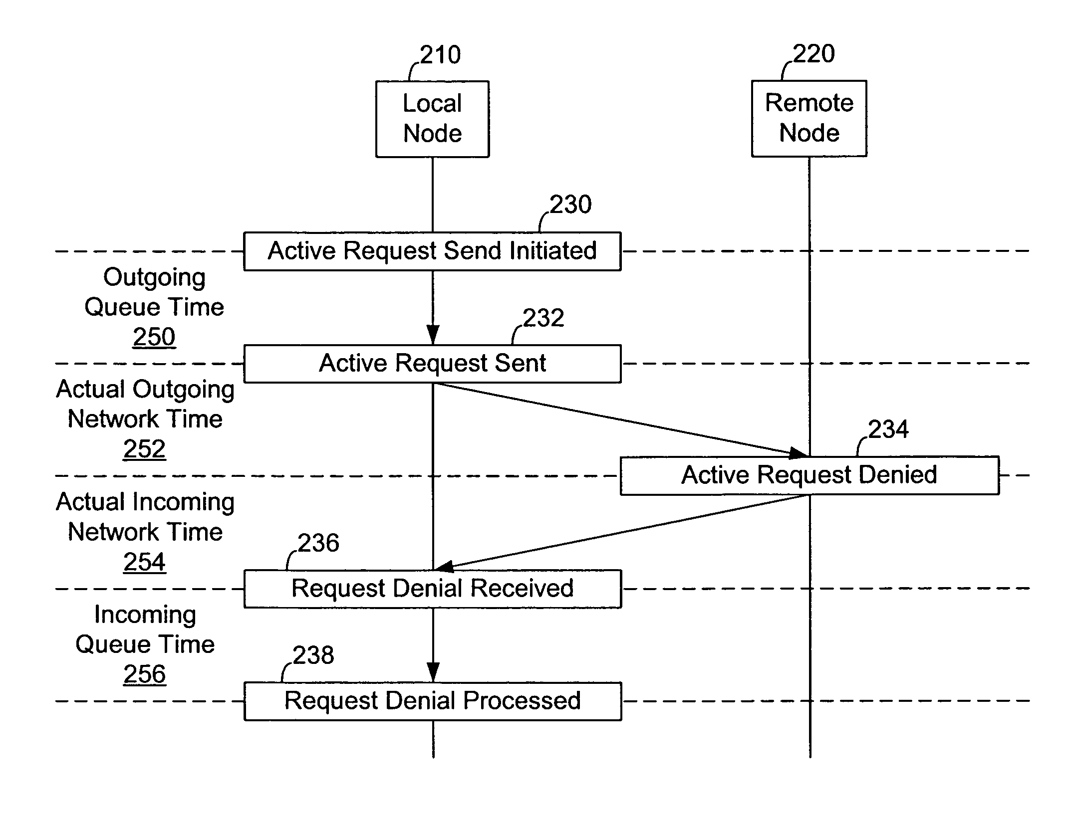
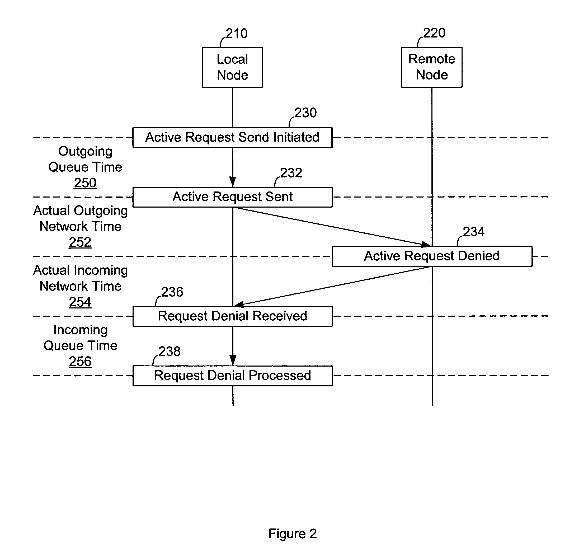
[0026]FIG. 2 shows the use of an active request to determine the local node queuing and network components of network application latency. Calculation of the local node and network components also enables calculation of remote node latency based upon comparison with application packet data. The local node 210 is the node generating the active request, such as a client computer system, workstation, or other computing resource. The remote node 220 receives and responds to the active request. The remote node 220 is a remote computing resource, such as a server, that is in communication with the local node 210 via a network.

[0027]An active request is a network request from the local node 210 to the remote node 220. Active requests are made on a periodic basis in association with a running application and a particular remote node or IP address. The active requests are calculated to generate a response by the remote node with minimal processing, thus minimal remote node time. Even TCP / IP ...


PUM


Abstract

A system and method of active latency detection for network applications that allows network latency to be calculated from a single host system. Periodic requests are generated from the host system and directed to a remote system in a way that requires minimal processing by the remote system. Latencies are calculated from the timing information associated with the periodic requests and can be combined with timing information associated with application packets to generate a latency trace for one or more network applications.

Description

BACKGROUND OF THE INVENTION[0001]1. Field of the Invention[0002]The invention relates to the field of network application monitoring and, more specifically, systems and methods for measuring client, network, and server times from a single source.[0003]2. Description of the Related Art[0004]An accurate picture of client, network, and server times is highly desirable for managing systems that rely on network applications. Such performance analysis allows administrators to identify bottlenecks and allocate resources to improve performance. However, identifying whether latency is caused by the client system, the network, or the remote server can be difficult using a single source.[0005]FIG. 1 shows an example exchange between a local node 110 and a remote node 120 for a network application. The client portion of the network application generates 130 a request. There is a local time delay before the request is actually sent 132 into the network. There is a network time delay before the r...

Claims


Application Information

Patent Timeline
Patent Type & Authority Patents(United States)
IPC IPC(8): G06F15/173
CPCH04L43/0858H04L43/0864H04L43/0894H04L43/10H04L69/28
Inventor RUSTAD, JOSEPH V.KAISER, GARYMURPHY, LESLIE L.MILLS, ROBERT C.SNYDER, MATTHEW J.LIN, GEORGE D.
Owner DYNATRACE
Why Eureka
Try Eureka