Surface relief grating image machining process and product

a surface relief grating and machining technology, applied in the field of images, can solve the problems of not being able to directly apply images, disrupting holographic images, and no process available to produce holographic images

Inactive Publication Date: 2008-05-06
KOZLOWSKI ANDY G
View PDF48 Cites 6 Cited by
  • Summary
  • Abstract
  • Description
  • Claims
  • Application Information

AI Technical Summary

Benefits of technology

[0008]A product with a SRG image has a surface with rotational cuts effected therein to create the SRG image effect. The SRG image has an effect based on a rotational speed of a cutting tool effecting the cuts, a travel speed of a cutting tool effecting the cuts, and a depth of the cuts. A light source can be used to emit light on the surface of the product.

Problems solved by technology

The image cannot be directly applied to a substrate having a rough surface because the rough surface of the substrate will refract light and will not have a highly reflective finish, thereby disrupting the holographic image.
Currently, no processes are available which produce holographic images on the surface of a material by cutting material out of the surface of the material.

Method used


Image

  • Surface relief grating image machining process and product
  • Surface relief grating image machining process and product
  • Surface relief grating image machining process and product

Examples


Embodiment Construction

[0018]The present invention is a SRG image machining process and / or product. The invention disclosed herein is, of course, susceptible of embodiment in many different forms. Shown in the drawings and described herein below in detail are preferred embodiments of the invention. It is to be understood, however, that the present disclosure is an exemplification of the principles of the invention and does not limit the invention to the illustrated embodiments.

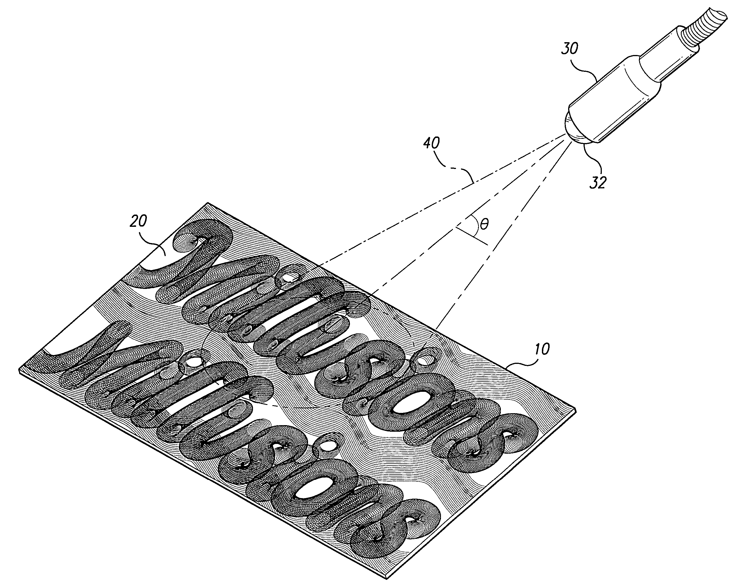
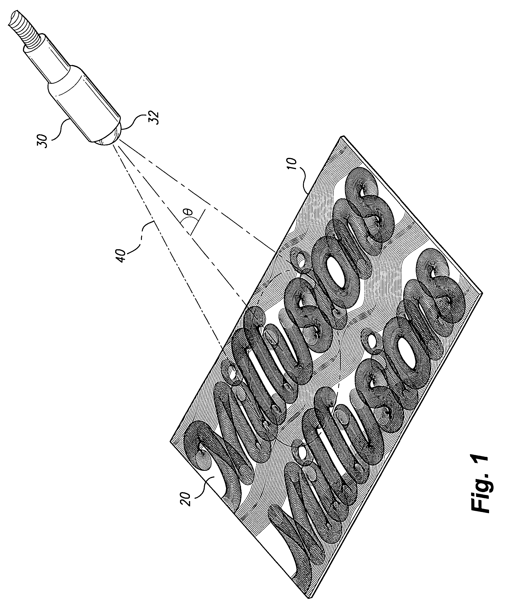
[0019]Referring now to the drawings, FIG. 1 shows a material 10 machined with a SRG and a light source 30 emitting light 40 onto the material 10 and illuminating the image. The SRG image is machined on the surface 20 of the material 10. The light source 30 includes a light element 32 (e.g., a light bulb or the like). To view the effects of the illumination of the SRG image on the surface 20 of the material 10, the position of the light source 30 can be adjusted to alter the angle of incidence of the emitted light 40. By altering the...


PUM

PropertyMeasurementUnit
surface reliefaaaaaaaaaa
depthaaaaaaaaaa
rotational speedaaaaaaaaaa

Abstract

A surface relief grating (SRG) image machining process and / or product. For the SRG image machining process a material and a cutting tool are provided. The material is contacted by the cutting tool to a predetermined depth. The cutting tool is rotated to cut the material at a predetermined rotational speed. The cutting tool is moved to cut the material at a predetermined travel speed. A SRG image effect is produced in the material through the contacting, rotating, and moving steps. A product with a SRG image effect has a surface with rotational cuts effected therein to create the SRG image effect. The SRG image has an effect based on a rotational speed of a cutting tool effecting the cuts, a travel speed of a cutting tool effecting the cuts, and a depth of the cuts. A light source can be used to emit light on the surface of the product.

Description

BACKGROUND OF THE INVENTION[0001]1. Field of the Invention[0002]The present invention relates generally to images formed by particular arrangements of reflective surface relief diffraction gratings and, more particularly to a surface relief grating image effect machining process and / or product.[0003]2. Description of Related Art[0004]Holographic images are three-dimensional images visible from an oblique angle. They appear to float in space and can change perspective. Numerous techniques for producing products with holographic images are known in the art. For example, a layer of plastic can be passed through a machine which imparts an image within the covering or upper strata of the plastic layer. A powdered metallic constituent or component is then applied thereon by a metalizing process. After metalizing, a holographic or three-dimensional image is imparted on the metalized layer of plastic. Such a holographic image is widely used within the credit card and security industries sin...

Claims


Application Information

Patent Timeline
Patent Type & Authority Patents(United States)
IPC IPC(8): B23C3/13B23C3/34
CPCB23C3/00B44B3/009B44B3/02Y10T409/303808Y10T29/49995
Inventor KOZLOWSKI, ANDY G.
Owner KOZLOWSKI ANDY G
Why Eureka
Try Eureka