Shrink fit tool holder with grooves

a tool holder and groove technology, applied in the field of shrink-fitting tool holder with grooves, can solve the problems of requiring a significant force to remove the tool, and may become an issue, and achieve the effect of reducing the amount of conductive heat transfer

Inactive Publication Date: 2008-05-06
KENNAMETAL INC
View PDF35 Cites 22 Cited by
  • Summary
  • Abstract
  • Description
  • Claims
  • Application Information

AI Technical Summary

Benefits of technology

[0005]In another aspect of the invention, a shrink fit tool holder comprises a body including a tool holder portion, and a central bore or aperture for accommodating a cutting tool, the central bore including a plurality of grooves formed in a predetermined pattern, wherein the plurality of grooves decreases a surface contact area between the tool holder portion and the cutting tool, thereby reducing an amount of conductive heat transfer between the tool holder portion and the cutting tool.

Problems solved by technology

The expanding tool shank can create problems with the removal of the tool from the chuck, even resulting in the tool remaining grasped by the chuck and requiring a significant force to remove the tool or a high temperature applied to the tool holder
In small tools, the removal may become an issue as the thermal expansion approaches the manufacturing tolerances.

Method used


Image

  • Shrink fit tool holder with grooves
  • Shrink fit tool holder with grooves

Examples


Embodiment Construction

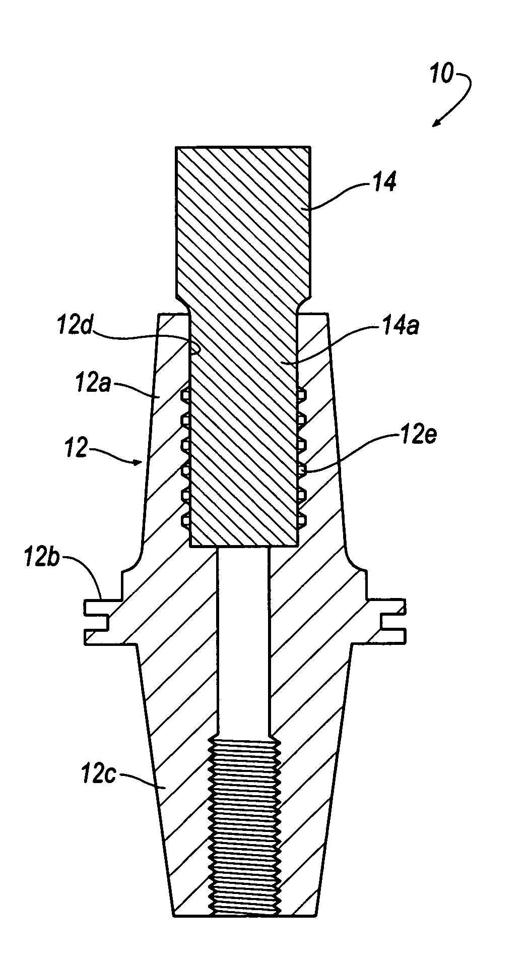
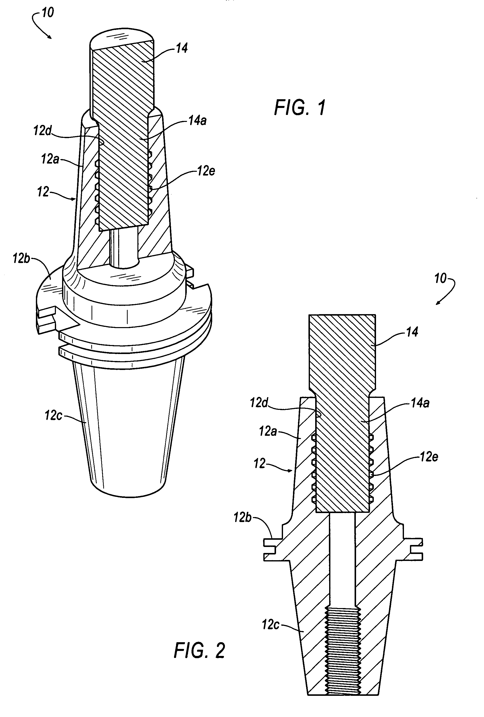
[0009]Referring now to FIGS. 1 and 2, there is shown an embodiment of a shrink fit tool holder, shown generally at 10, for detachably retaining a rotary cutting tool 14 according to the invention. In general, the shrink fit tool holder 10 comprises a shank or body 12 that includes a tool holder portion 12a, a flange member 12b, a tapered outer surface 12c that generally corresponds to a tapered bore of a spindle (not shown), and a central bore or aperture 12d for accommodating the cutting tool 14.

[0010]The central aperture 12d is formed to be approximately 0.0001-0.0020 inches (0.00254-0.0508 mm) less in diameter than a shank portion 14a of the cutting tool 14. This amount depends on the nominal size and the required torque transmission capacity. In order to insert the cutting tool 14 within the tool holder 10, the tool holder portion 12a of the tool holder 10 is externally heated, for example, to a temperature of approximately 650° F. Due to the thermal expansion characteristics of...


PUM

PropertyMeasurementUnit
diameteraaaaaaaaaa
temperatureaaaaaaaaaa

Abstract

A shrink fit tool holder includes a shank or body that includes a tool holder portion, a flange member, a tapered outer surface that generally corresponds to a tapered bore of a spindle, and a central bore or aperture for accommodating a cutting tool. The central bore includes a plurality of grooves formed in a predetermined pattern that decrease a surface contact area between the tool holder portion and the cutting tool, thereby reducing an amount of conductive heat transfer between the tool holder portion and the cutting tool. As a result, there is less expansion in the tool shank relative to the tool holder.

Description

BACKGROUND OF THE INVENTION[0001]It is known in the art to utilize heat shrink or shrink fit tool assemblies in industrial applications. The prior designs have utilized unitary chucks having an inner diameter slightly smaller than the exterior diameter of the shank of the cutting tool or other work piece. During use the tool chuck is heated, typically by means of induction heating, causing the chuck to expand a sufficient amount to allow the tool shank to be inserted within the chuck. The tool is then allowed to cool during which the thermal contraction of the chuck exerts a uniform pressure on the tool shank, allowing the chuck to shrink down around the tool shank to securely lock or hold the shank in place. It has long been recognized that these types of heat shrink tool assemblies provide an improvement in accuracy and rigidity over standard milling chucks or collet chucks.[0002]In order to remove the tool, the chuck is re-heated to expand the opening. During the heating process ...

Claims


Application Information

Patent Timeline
Patent Type & Authority Patents(United States)
IPC IPC(8): B23B31/117
CPCB23B31/02B23B31/1179B23P11/027B23B2260/072Y10T29/49865Y10T279/17965Y10T409/30952
Inventor RUY FROTA DE SOUZA, FILHO
Owner KENNAMETAL INC
Why Eureka
Try Eureka