Ion beam measuring method and ion implanting apparatus

a technology of ion beam and measuring method, applied in the field of ion beam measuring, can solve the problems of reducing productivity, increasing cost, and complicated structur

Inactive Publication Date: 2008-05-06
NISSIN ION EQUIP CO LTD
View PDF11 Cites 4 Cited by
  • Summary
  • Abstract
  • Description
  • Claims
  • Application Information

AI Technical Summary

Benefits of technology

[0025]It is an object of the invention to provide an ion beam measuring method capable of measuring at least one, preferably foregoing two, and further preferably three of angle deviation, a diverging angle and a beam size in y direction orthogonal to a direction of scanning an ion beam by a simple constitution.
[0034]According to an ion implanting apparatus having the control apparatus for executing the first ion beam measuring method and predetermined ones in processings in correspondence with the steps of the method, the angle deviation θy in y direction orthogonal to the scanning direction of the ion beam can be measured. Further, the measurement is carried out by utilizing the forestage multipoints Faraday and the poststage multipoints Faraday provided for measuring a parallelism or the like in the scanning direction of the ion beam and therefore, it is not necessary to newly provide a Faraday measuring system. Therefore, the measurement can be carried out by a simple constitution. Further, it is not necessary to execute the operation of interchanging a measuring system in x direction and a measuring system in y direction relative to the beam line and therefore, an extra time period is reduced and productivity is promoted by that amount.
[0036]According to an ion implanting apparatus having a control apparatus for executing the third ion beam measuring method and predetermined ones of processings in correspondence with the steps of the method, the beam size dyt in y direction of the ion beam on the target can be measured. Further, the measurement is carried out by utilizing the forestage multipoints Faraday and the poststage multipoints Faraday provided for measuring a parallelism or the like in the scanning direction of the ion beam and therefore, it is not necessary to newly provide a Faraday measuring system. Therefore, the measurement can be carried out by a simple constitution. Further, it is not necessary to execute operation of interchanging a measuring system in x direction and a measuring system in y direction relative to the beam line and therefore, an extra time period is reduced and productivity is promoted by that amount.

Problems solved by technology

However, when a Faraday measuring system quite separately from the forestage multipoints Faraday and the poststage multipoints Faraday which have been provided in the background art for measuring the parallelism in x direction of the ion beam 4 or the like is newly provided in order to measure the angle deviation θy in y direction, the diverging angle, and the beam size of the ion beam 4, (a) the measuring system is increased, the structure becomes complicated and also cost is considerably increased, (b) in measuring operation, an operation of interchanging the measuring system in x direction and the measuring system in y direction is obliged to be carried out with respect to the beam line of the ion beam 4, a time period required for the interchanging operation becomes an extra time period and the productivity is lowered.

Method used


Image

  • Ion beam measuring method and ion implanting apparatus
  • Ion beam measuring method and ion implanting apparatus
  • Ion beam measuring method and ion implanting apparatus

Examples


Embodiment Construction

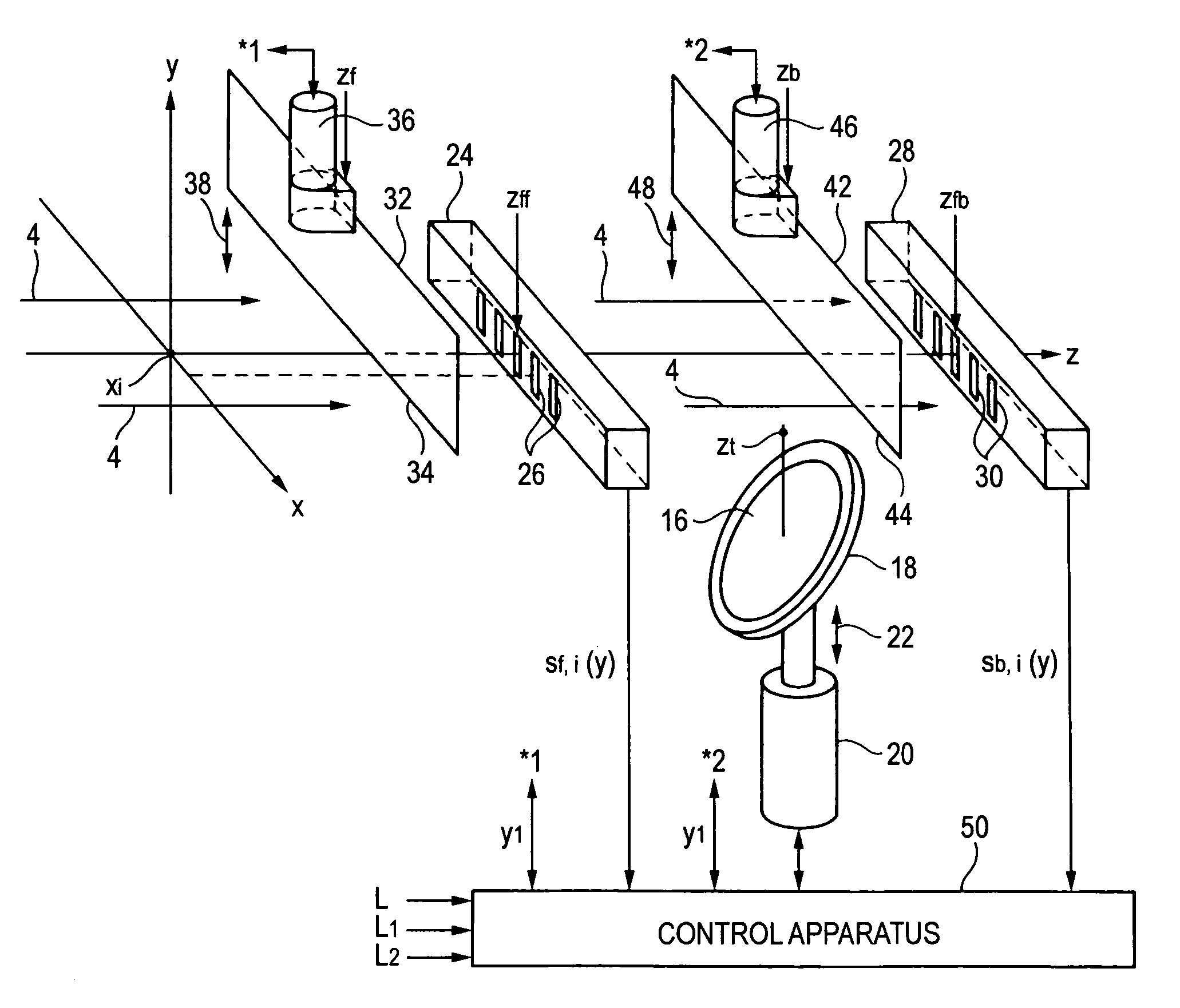
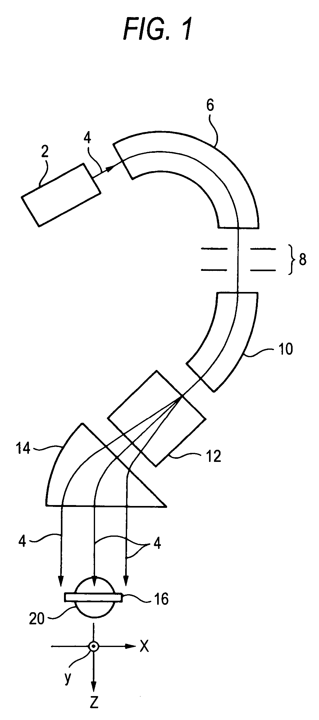
[0050]FIG. 7 is a view showing an essential portion of an embodiment of an ion implanting apparatus for embodying an ion beam measuring method according to the invention. A constitution of a total of the ion implanting apparatus refers to FIG. 1 and the explanation related thereto. Further, portions the same as or corresponding to those in the example shown in FIG. 1 are attached with the same notations and in the following, a difference thereof from those of the above-described example will mainly be explained.

[0051]The ion implanting apparatus includes the forestage multipoints Faraday 24 at a position zff on an upstream side of the target 16 and includes the poststage multipoints Faraday 28 at a position zfb on a downstream side of the target 16 with regard to a position on z axis constituting an advancing direction of the ion beam 4. A position on z axis of the target 16 is designated by notation zt. When the target 16 is inclined as in the example shown in FIG. 7, a position on...


PUM


Abstract

A beam current density distribution in y direction of an ion beam 4 at a position of a forestage beam restricting shutter 32 is measured by measuring a change in a beam current of the ion beam 4 incident on a forestage multipoint Faraday 24 by passing an outer side of a side 34 of the shutter 32 while driving the forestage beam restricting shutter 32 in y direction by a forestage shutter driving apparatus 36. Further, a beam current density distribution in y direction of the ion beam 4 at a position of a poststage beam restricting shutter 42 is measured by measuring a change in the beam current of the ion beam 4 incident on a poststage multipoints Faraday 28 by passing an outer side of a side 44 of the shutter 42 while driving the poststage beam restricting shutter 42 in y direction by a poststage shutter driving apparatus 46. Further, at least one of an angle deviation, a diverging angle and abeam side in y direction of the ion beam 4 is measured by using a result of the measurement.

Description

TECHNICAL FIELD[0001]The present invention relates to an ion beam measuring method of measuring an angle deviation, a diverging angle and a beam size of an ion beam in y direction orthogonal to x direction in an ion implanting apparatus of a type of parallelly scanning the ion beam in x direction to irradiate to a target and an ion implanting apparatus capable of carrying out the measuring method by using a control apparatus.BACKGROUND ART[0002]An ion implanting technology holds an important position in a semiconductor fabricating process or the like in recent times.[0003]In implanting ions to a target, for example, a semiconductor substrate, it is known that an implantation characteristic particular in an implantation depth direction is indicated by an implantation angle (incidence angle) relative to a crystal axis of the semiconductor substrate and it is normally requested for the ion implanting technology to enable to execute an ion implanting processing under a condition of prev...

Claims


Application Information

Patent Timeline
Patent Type & Authority Patents(United States)
IPC IPC(8): H01J3/10G21K1/04G01T1/29G21K5/04H01J37/04H01J37/244H01J37/317H01L21/265
CPCH01J37/244H01J37/3171H01J2237/24405H01J2237/2446H01J2237/24507H01J2237/31703H01L21/26586H01L21/265
Inventor UMISEDO, SEIHAMAMOTO, NARIAKI
Owner NISSIN ION EQUIP CO LTD
Why Eureka
Try Eureka