
Voltage control apparatus for electric generator of vehicle

a voltage control apparatus and electric generator technology, applied in the direction of electric generator control, dynamo-electric converter control, transportation and packaging, etc., can solve the problem of inability to achieve the necessary degree of restraint of the generator output voltage (to achieve the required improvement of engine starting performance) and inability to stabilize the engine starting

Inactive Publication Date: 2008-05-06
DENSO CORP
View PDF18 Cites 26 Cited by
  • Summary
  • Abstract
  • Description
  • Claims
  • Application Information

AI Technical Summary

Benefits of technology

Enhances engine starting performance across various conditions, including low-temperature operations, while minimizing the risk of battery discharge by ensuring the low voltage setting is only applied during engine starting and for short intervals, thus maintaining optimal generator output.

Problems solved by technology

However if the level of torque that must be applied to the electric generator from the engine becomes excessive, then this can result in instability of engine starting.
As a result, if the duration of each fixed interval of restraint of the generator output voltage is long, thereby reducing the amount of charging current that is supplied to the vehicle battery, then the level of charge in the battery may become excessively low.
In such a condition, the necessary degree of restraint of the generator output voltage (to achieve a required improvement in engine starting performance) cannot be achieved by applying only a small reduction in the regulated value of the generator output voltage.
However in that case there is a danger that the regulated value of the generator output voltage might become fixed at the very low value, as a result of some abnormality occurring in the connecting leads or connection terminals that transfer the control signal from the ECU.
In such a case, almost no generator power would be produced by the electric generator, so that serious problems in operating the vehicle could arise, with the battery becoming completely discharged.
Hence with such a method, it is not practicable to set the regulated value of the generator output voltage at a very low value.

Method used


Image

  • Voltage control apparatus for electric generator of vehicle
  • Voltage control apparatus for electric generator of vehicle
  • Voltage control apparatus for electric generator of vehicle

Examples


first embodiment

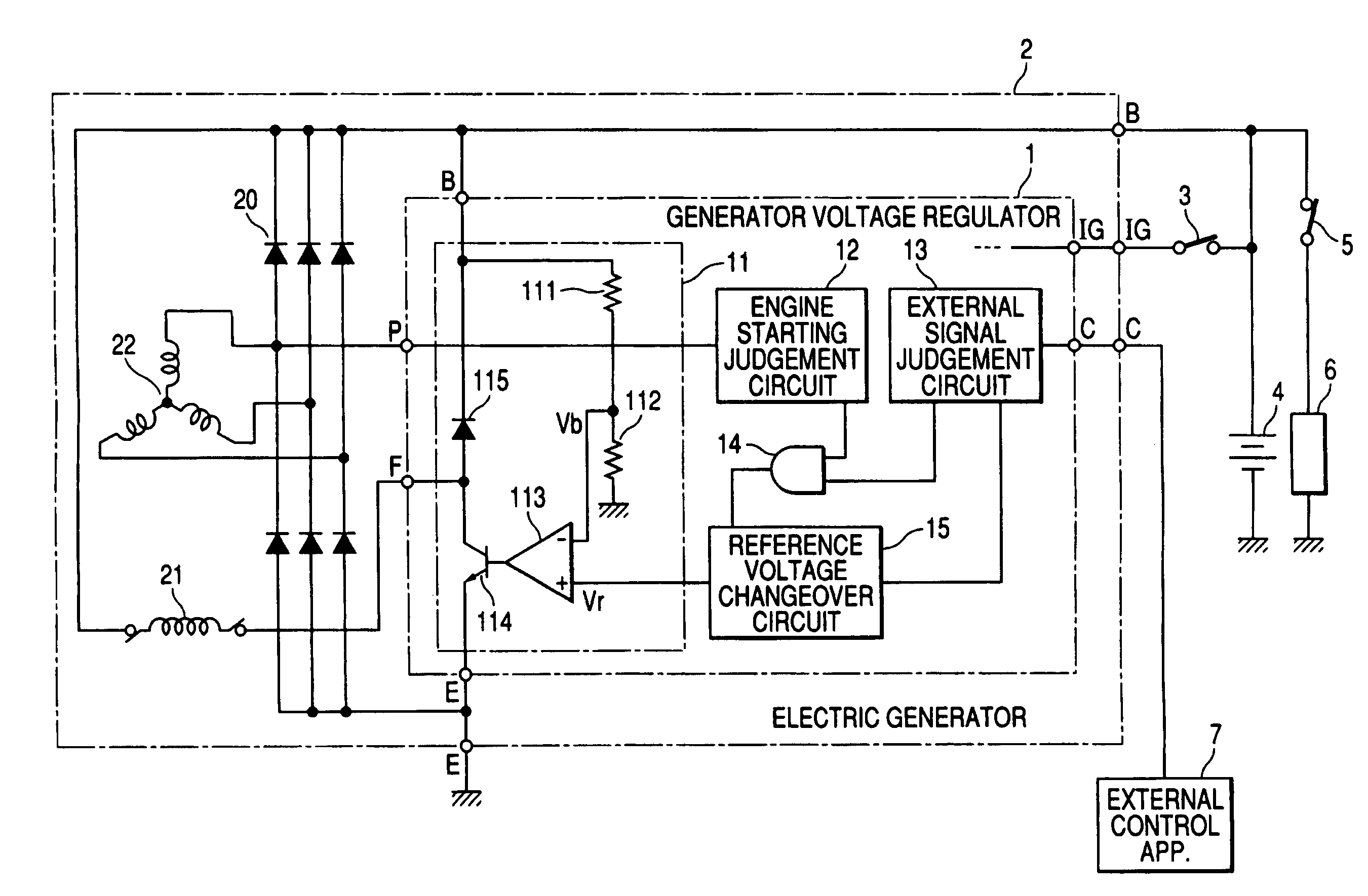
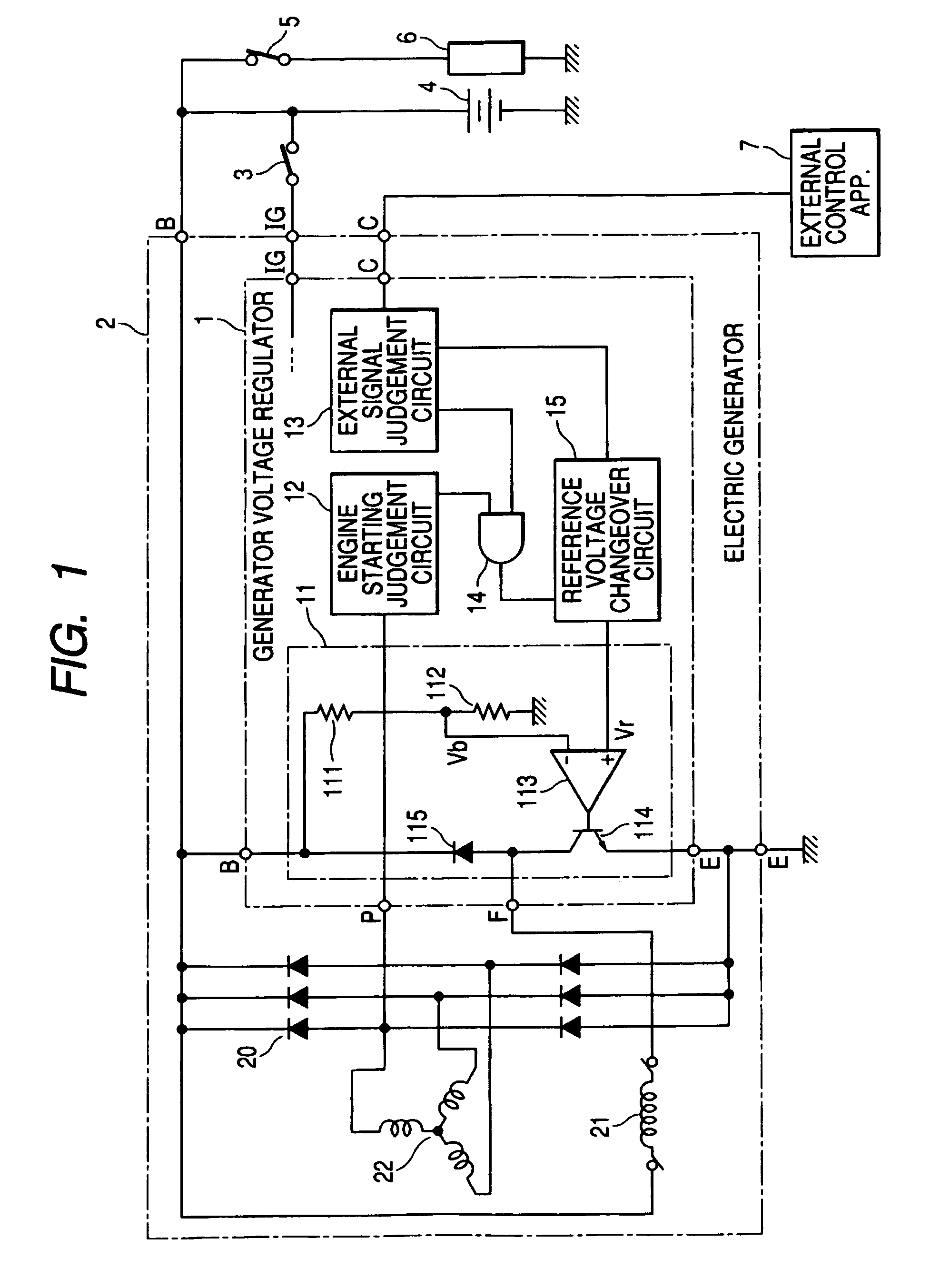
[0026]FIG. 1 shows the general configuration of a first embodiment of a generator voltage regulator 1 incorporated in an electric generator 2 of a vehicle. FIG. 1 also shows the connections between the electric generator 2 and an external apparatus 7, such as an engine ECU of the vehicle.

[0027]The electric generator 2 is based on a 3-phase AC generator which is driven by a drive belt and pulleys from the vehicle engine, with only the field winding 21 and armature winding 22 of that AC generator being shown, and a full-wave rectifier 20 which converts the AC output voltage from the AC generator to an unsmoothed DC voltage that is supplied to an output terminal (B terminal) of the electric generator 2.

[0028]The field winding 21 is formed on the poles of the rotor (not shown in the drawings) of the AC generator, while the armature winding 22 is a 3-phase wave-wound coil that is formed on the iron core of the armature (not shown in the drawings) of the AC generator. As is well known, th...

second embodiment

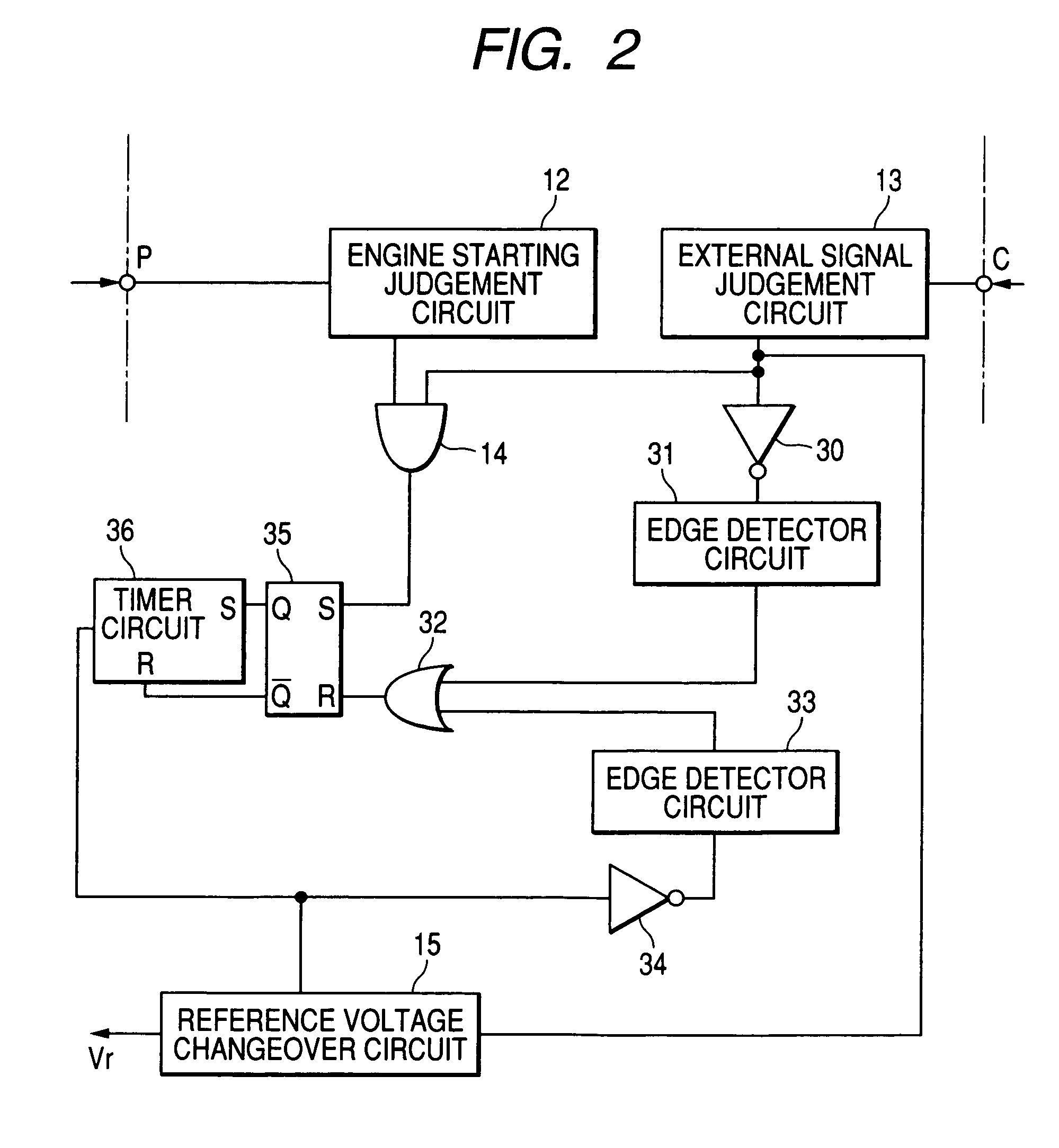
[0051]With a second embodiment, the engine starting judgement circuit 12 is configured to detect each engine starting interval based on the level of output voltage of the electric generator 2. That is to say, each engine starting interval is detected as commencing when the engine begins to rotate (as indicated by the frequency of the AC voltage appearing on a phase winding as described above for the first embodiment), and ending when the output voltage of the electric generator 2 reaches a predetermined value that is equal to or close to a normal operating value (determined by the first reference voltage Vref1 as described above).

[0052]With this embodiment, in addition to receiving an AC signal produced from a phase winding 22 of the AC generator, the engine starting judgement circuit 12 is supplied with the output voltage from the electric generator 2, for use in judging the level of that voltage. Alternatively, the voltage Vb appearing at the junction of the resistors 111, 112 may...

third embodiment

[0054]With the above embodiments, at a time point when the generator output restraining signal ceases to be transmitted to the electric generator 2, at the end of an engine starting operation (i.e., a time point at which the reference voltage changeover circuit 15 begins to receive a low level input signal from the external signal judgement circuit 13) the target value of generator output voltage is changed from that determined by the lowest (third) reference voltage Vref3 to that determined by the normal (first) reference voltage Vref1.

[0055]With a third embodiment, which is a modified form of the second embodiment above, when the interval of regulating the generator output voltage in accordance with the third reference voltage Vref1 is ended (e.g., when the external control apparatus 7 determines that driving of the starter motor has ended), the external control apparatus 7 begins to transmit the generator output restraining signal intermittently rather than continuously. That is ...


PUM


Abstract

In a vehicle voltage control apparatus which regulates the output voltage of the vehicle electric generator and which receives an external control signal for lowering the regulated voltage value, from an external apparatus such as the engine ECU during engine starting, a circuit detects the occurrence of engine starting based upon the frequency of an AC voltage produced by the generator or upon the level of output voltage produced by the generator. The regulated voltage value is set to a substantially low level, predetermined for use during engine starting, only while the control signal is being received concurrent with engine starting also being detected.

Description

CROSS-REFERENCE TO RELATED APPLICATIONS[0001]This application is based on and incorporates herein by reference Japanese Patent Application No. 2005-261459 filed on Sep. 9, 2005.BACKGROUND OF THE INVENTION[0002]1. Field of Application[0003]The present invention relates to a voltage control apparatus for installation on a motor vehicle such as an automobile, truck, etc.[0004]2. Description of Related Art[0005]The electric generator of a motor vehicle is generally a combination of an AC generator apparatus that is driven from the vehicle engine, and a rectifier apparatus, with the electric generator thereby producing a DC voltage which is supplied to charge the vehicle battery and to drive various electrical loads of the vehicle. The higher the level of output current that must be supplied to charge the battery and to drive the electrical loads, the greater will be the level of torque that must be applied from the engine to the rotor of the electric generator (i.e., of the AC generator...

Claims


Application Information

Patent Timeline
Patent Type & Authority Patents(United States)
IPC IPC(8): H02P9/00H02J7/14
CPCH02J7/1446H02J7/245H02P9/48H02P2101/45Y02T10/92H02J7/2434
Inventor TSUZUKI, TOMOMI
Owner DENSO CORP
Learn More