Distributed intelligence ballast system and extended lighting control protocol

a ballast system and intelligence technology, applied in the field of multi-ballast lighting and control system, to achieve the effect of increasing responsiveness, facilitating communication, and facilitating communication

Active Publication Date: 2008-05-06
LUTRON TECH CO LLC
View PDF77 Cites 214 Cited by
  • Summary
  • Abstract
  • Description
  • Claims
  • Application Information

AI Technical Summary

Benefits of technology

[0021]According to another advantage of the present invention, maintenance of a lighting system using the extended protocol system is more efficient and more easily achieved due to the localized rather than centralized control. One type of advantage contemplated in accordance with the present invention is an additional controller that can be attached to the extended DALI protocol network to act as a peer to peer controller to provide a gate keeping function between various devices on the network. In such a configuration, peer to peer operations increase responsiveness in the DALI lighting system to provide greater functionality and flexibility for the entire system.
[0022]Other features and benefits of the present invention are realizable by the combination of individual ballasts that include processing power, and the configuration of the ballasts to utilize the extended DALI protocol. For example, ballasts are configured in a default “out-of-box” mode to perform various functions upon installation and without additional configuration and setup. More particularly, a ballast is configured with a photosensor input and broadcasts its sensor data over the shared interface automatically. Further, ballasts are configured upon installation without configuration to function as a standard DALI ballast such that information that is broadcast over a DALI compatible communication link is automatically received by an “out-of-box” ballast that has not yet been “commissioned” (i.e., configured with an address and various programming instructions).
[0023]Yet another feature of the present invention is that commissioning of the distributed system is greatly simplified. Assigning an address to a ballast installed on a DALI communication link can be performed in various ways, including by entering commands on a keypad, using an infra-red transmitter to send commands to an infra-red receiver input on a ballast, and by transmitting commands using another device having a processor and memory, such as a properly configured power supply and / or controller device.
[0024]Further, the present invention improves the commissioning of replaced ballasts. In one embodiment, for example, a database is referenced that stores configuration information for every ballast on a communication link. After a replacement ballast is added to the database, any configuration information relating to the replaced ballast is automatically assigned to the replacement ballast. In this way, a plurality of ballasts that replace faulty ballasts can be commissioned quickly and accurately.
[0025]Yet another benefit of the present invention includes the use of programming routines that can be used, for example, by a single ballast that is configured to receive sensor readings from a plurality of photocells, and, thereafter to average and broadcast the averaged readings to other devices on the link. Thus, for example, a ballast can provide an accurate representation of the amount of light that is produced from a single lamp or plurality of lamps and from another source, such as natural sunlight.
[0026]Another feature of the present invention includes scaling input values to accommodate various operation range limitations of the installed ballasts. For example, one ballast that has a range of operation that is smaller than another ballast receives an input command that is scaled to factor into consideration the limitations of the ballast's range of operation. By scaling input values for various devices on the communication link, the present invention improves accuracy, for example, with respect to commands sent and received by various ballasts.

Problems solved by technology

More particularly, those devices that are capable of only receiving DALI protocol messages ignore messages that are formatted according to the extended protocol.

Method used


Image

  • Distributed intelligence ballast system and extended lighting control protocol
  • Distributed intelligence ballast system and extended lighting control protocol
  • Distributed intelligence ballast system and extended lighting control protocol

Examples


Embodiment Construction

System Overview

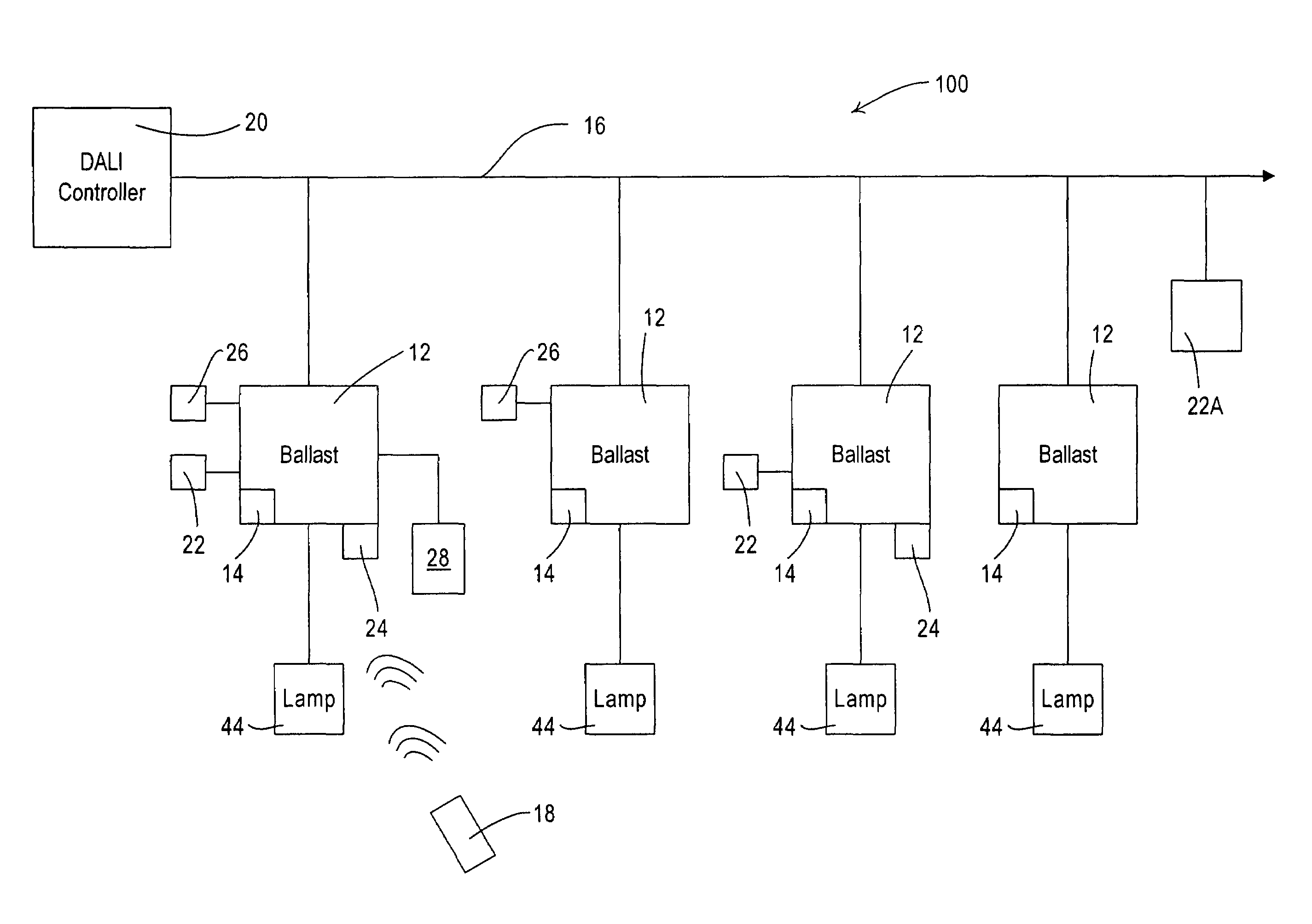
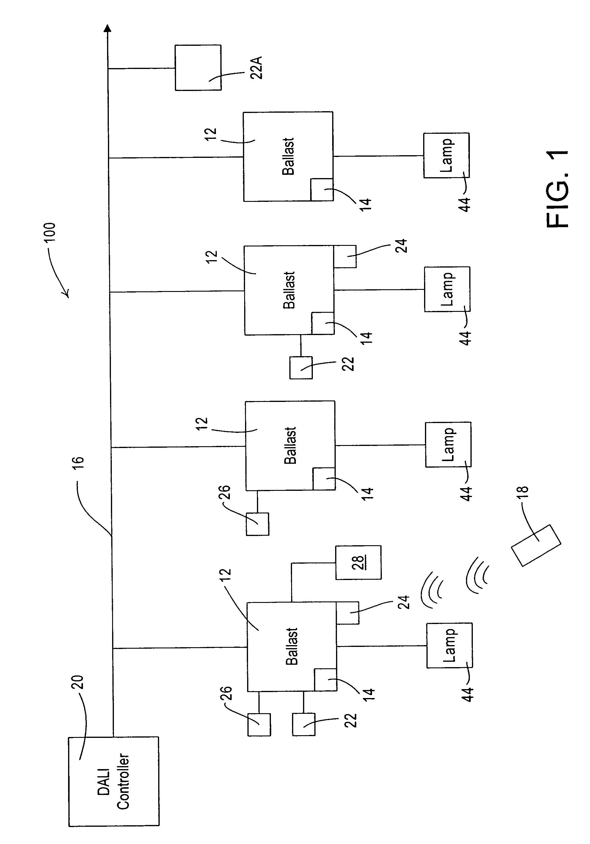
[0040]Referring to the drawing figures, in which like reference numerals refer to like elements, FIG. 1 is a diagram of a distributed ballast system 100 in accordance with an exemplary embodiment of the present invention. As shown in FIG. 1, a plurality of ballasts 12 that comprise processors 14 are installed on a communication link 16, preferably a DALI communication link. Coupled to each ballast is a lamp or lamps 44, and some or all of the ballasts 12 have sensors attached thereto. For example, photocell sensors 22 and occupancy sensors 26, as well as infrared receivers 24 are shown attached to some ballasts 12. Also as shown in FIG. 1, at least one ballast is provided that has no sensor input, and at least one photosensor 24A is provided that is attached to link 16 as a stand alone device. Thus, devices are provided on communication link 16 in various combinations.

[0041]The DALI communications link 16 is bi-directional, and an incoming signal can comprise a comman...


PUM


Abstract

A ballast for use in a multi-ballast lighting system wherein the ballasts are coupled together by a digital communication network. The ballast comprises a power circuit portion for providing an electrical current to power a lamp. The ballast further includes a sensor input circuit for receiving at least one sensor input from a sensor device, a processor receiving an input from the sensor input circuit and providing control signals to control the operation of the ballast, and a communication port coupled to the processor and to the communication network for exchanging data. The ballast processor is operative to receive a serial data that has a portion defining whether the message is in a first or a second format, the first format comprising a DALI standard format and the second format comprising a format providing extended functionality. The ballast processor is capable of processing messages in either the first or second formats.

Description

BACKGROUND OF THE INVENTION[0001]1. Field of the Invention[0002]The present invention relates generally to a multi-ballast lighting and control system, and, more particularly, to a distributed intelligence multi-ballast lighting system employing a DALI backward compatible extended protocol for messages in a lighting control network that extends the functionality of the lighting control network.[0003]2. Description of Related Art[0004]In recent years, large-scale lighting systems have been developed to meet the needs of lighting applications with distributed resources and centralized control. For example, building lighting systems are often controlled on a floor by floor basis or as a function of the occupancy space used by independent groups in the building. Taking a floor of a building as an example, each room on the floor may have different lighting requirements depending on a number of factors including occupancy, time of day, tasks ongoing in a given room, security and so forth,...

Claims


Application Information

Patent Timeline
Patent Type & Authority Patents(United States)
IPC IPC(8): G08B5/22
CPCH05B37/0254H05B41/38H05B47/18
Inventor VESKOVIC, DRAGANANSELMO, ROBERTCASH, AUDWIN W.SKVORETZ, MATTHEW A.
Owner LUTRON TECH CO LLC
Why Eureka
Try Eureka